

Isolation
Isolation is a measure of the amount of power that leaks from one mixer port to another. As was previously described, port isolation is obtained through mixer balance and the use of hybrid junctions. Unfortunately, there is always some small amount of power leakage between the RF, LO and IF ports. Isolation is the difference in power between the input signal and the leaked power to the other ports. If, for example, a signal is input at the LO port and power at the LO frequency is measured at the RF port, isolation in dB is given by:
PISO (L-R) = PIN(@LO) – POUT(@ RF) (7)
Note that isolation is approximately reciprocal, i.e. port 1 to port 2 isolation tracks closely with port 2 to port 1 isolation. Hence, a single measurement can be performed to determine isolation in both directions. Three types of isolation are commonly quoted for microwave mixers: L-R isolation, L-I isolation and R-I isolation. Their definitions are illustrated in Figure 8.
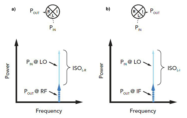
Figure. 8 Definitions of L-R (a), L-I (b) and R-I (c) isolation.
L-R isolation is the measure of LO leakage into the RF port. Typical L-R isolation ranges from 25 to 35 dB. L-R isolation is critical in frequency downconversion because LO power can leak into RF circuitry and contaminate the RF line by either interfering with the RF amplifier or by leaking to other parallel mixing channels causing cross-channel interference. Poor L-R isolation can also cause problems in frequency upconversion when the LO frequency is very close to the RF output frequency (i.e. the IF frequency is at or near DC). In this case, no amount of filtering can separate the arbitrarily close RF signal and LO leakage. This can result in interference between the RF and LO and a degradation of the RF output.
L-I isolation is the measure of LO leakage into the IF port. L-I isolation tends to be the worst of the three types, with typical values ranging from 20 to 30 dB. When there is poor L-I isolation, the biggest issue occurs when the LO and IF frequencies are so close that the LO contaminates the IF circuitry; for example, when the LO leakage is strong enough to saturate the IF amplifier. Beyond this, poor L-I isolation can cause conversion loss flatness problems.
The final mixer isolation metric is R-I isolation. Values of R-I isolation typically range from 25 to 35 dB. Most systems designers do not find R-I isolation to be a major issue since RF and IF powers tend to be orders of magnitude smaller than LO power.
While LO isolation is a primary concern of systems engineers, R-I isolation is a major concern for mixer designers because it serves as a diagnostic metric for the overall conversion efficiency of the mixer circuit. When R-I isolation is high, the mixer circuit is well balanced and thus the conversion loss tends to be low. In mixers with bad R-I isolation (less than 20 dB), conversion loss is higher and conversion loss flatness is poor.
1 dB Compression
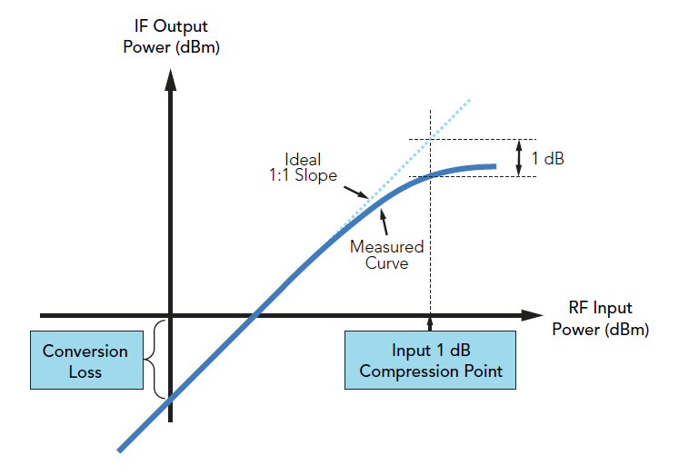
Figure 9. Graphical representation of 1 dB compression point.
Under normal (linear) operation, mixer conversion loss is constant, regardless of input RF power. If the input RF power increases by 1 dB, then the output IF power will also increase by 1 dB (the power difference is the conversion loss). However, as the RF power becomes too large, the dB for dB relationship does not hold. The 1 dB compression point is a measure of mixer linearity and is defined as the input RF power required to increase the conversion loss by 1 dB from ideal. Mixer compression is most easily represented graphically as shown in Figure 9. For low input RF power, the slope of the line is 1:1 as described above. However, as RF power increases, the mixer deviates from this linear behavior and conversion loss starts to increase. When the input/output curve “sags” by 1 dB (i.e the conversion loss increases by 1 dB), input RF 1 dB compression has been reached. Conceptually, the 1 dB compression point occurs when the RF signal can no longer be considered “small signal”. Under linear operation, the LO power is so much stronger than the RF power that the diode switching action is totally dominated by the LO, as previously described. In compression, however, RF power competes with LO power such that the diode switching action is compromised. When the RF power is within about 3 dB of 1 dB compression, the mixer behaves unpredictably.
Among other effects, operating the mixer in compression causes increased levels of intermodulation distortion and higher conversion loss. This behavior is explained by the fact that the compressed mixer spreads energy in the frequency domain because the diodes are partially turned-on by the RF signal. Slight mixer imbalances are therefore exacerbated and the mixer conversion efficiency is degraded. Mixer compression can be improved by using higher turn-on diodes. In this way, a larger RF power can be applied to the mixer without challenging the turn-on voltage of the diode. The trade-off, of course, is that a larger LO drive must also be applied to switch the diode ON and OFF. As a rule of thumb, the 1 dB compression point will be anywhere from 4 to 7 dB below the minimum recommended LO drive level of the mixer. For low barrier “L” diodes, 1 dB compression occurs for input RF powers greater than 0 dBm. For super-high barrier “S” diodes, 1 dB compression occurs for input RF power levels greater than +12 dBm.
VSWR
Mixer VSWR is a contentious topic. Some are of the opinion that it is a meaningless metric for microwave mixers because it does not help to predict mixer performance nor does it guarantee proper operation when the mixer is integrated within the surrounding RF system. The crux of the argument comes down to the fact that the mixer cannot be modeled as a static load. In actuality, a mixer is both a load and a source. It can be shown that all three mixer ports act as sources for the intermodulation distortion intrinsic to the diodes.1 Even if the VSWR of the mixer is perfect (i.e. no reflections of the fundamental), there will inevitably be harmonics coming
out of the input ports.
A classic mixer spur problem involves the 2LO x 1RF “image” spur. It can be shown that all EVEN LO x ODD RF spurs generated within the mixer are available at the RF port.1 A problem arises when the RF port is reactively terminated with, for example, a preselection bandpass filter. Acting as a source, the mixer produces the 2L x 1R image spur which exits the RF port and enters the RF filter. Most commonly, the 2L x 1R product lies outside the passband of the filter and is hence reflected back into the mixer as shown in Figure 10.
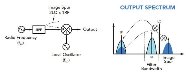
Figure. 10 Schematic showing backreflected 2LO x 1RF spur from reactive bandpass filter (a). Output spectrum showing desired IF and downconverted image spur overlapping in frequency (b).
Upon re-entry into the mixer, the 2L x 1R image product mixes with the LO and downconverts to the exact same frequency as the desired difference frequency. In other words:
fout = fspur - fLO
fout = 2fLO - fRF - fLO
fout = fLO - fRF
fout = fIF (8)
The overlap of the downconverted image spur and the desired IF creates substantial interference. The extent of interference depends on the relative phase difference between the two signals. If the RF frequency is swept, the relative phase will cycle from 0 to 2π resulting in significant conversion loss ripple. A common concern is that conversion loss ripple is caused by poor mixer VSWR. However, as illustrated in this example, issues associated with the mixer acting as a source of RF and LO products frequently lead to more serious problems if precautions are not taken such as increasing attenuation or using non-reflective terminations.
Noise Figure
As long as the quality of the diode is closely monitored, mixer noise figure can be approximated by its conversion loss. Generally, the cumulative noise figure will limit the minimum detectable signal in the receiver. Hence, when choosing mixers for low power applications, conversion loss should be as low as possible.
Single-tone Intermodulation Distortion
Much has already been said about the harmonic mixing products generated by nonlinear mixing of RF and LO signals in the transition region of the diode I-V curve as given by (5) and illustrated in Figure 3. Most commonly, the only desirable mixing term is given by m=1 and n=1 and all other unwanted harmonic terms are called single-tone IMD. A major goal in mixer design is to limit the strength of the single-tone IMD terms. The key features of single-tone IMD in double and triple balanced mixers are:
1. Only ODD n by m terms exist at the IF port in double and triple balanced mixers.
2. Cancellation through mixer balance improves EVEN by EVEN, EVEN by ODD and ODD by EVEN harmonic levels by about 30 dB.
3. The lower the RF input power, the better the single-tone spurious performance.
4. Increasing the LO drive does not always improve spurious performance.
For additional information on single-tone IMD in double balanced mixers, see Bert Henderson’s analysis on the prediction of mixer IMD.4
Multi-Tone Intermodulation Distortion
Multi-tone IMD implies that multiple tones enter the mixer through the same port and intermodulate in the mixer diodes. Multi-tone IMD is a form of common mode mixing in which two or more tones enter the RF port and nonlinearly mix with each other and the LO to create distortion (see Figure 11).
a)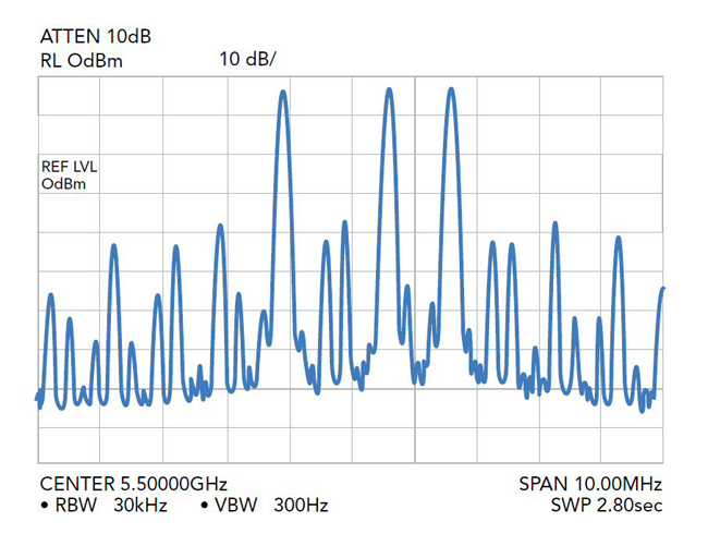
b)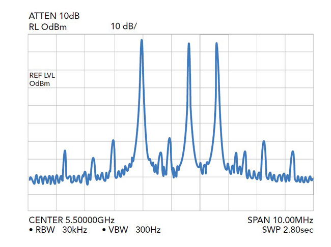
Figure 11. Significant multi-tone IMD caused by three input RF signals (a). IMD performance using a mixer with improved commutating behavior (b).
From the perspective of a system designer, multi-tone IMD is a serious problem because it can generate interference tones that fall within the IF bandwidth of the receiver. Hence, multi-tone IMD places a theoretical upper limit on the dynamic range of the receiver.
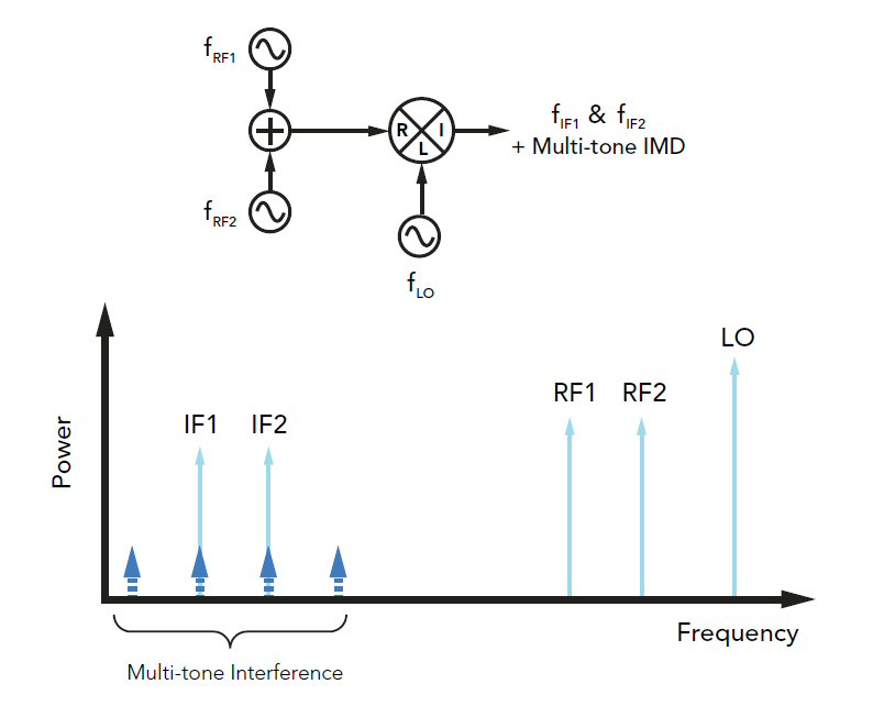
Figure 12. Illustration of multi-tone IMD created by two closely spaced RF signals. Generated IMD tones overlap with desired IF1 and IF2 signals.
The efficiency of multi-tone IMD generation is dependent on the intrinsic nonlinear characteristics of the devices (i.e. diodes, FETs) and the balance of the mixer. The widely accepted figure of merit for mixer multi-tone performance is the two tone third order input intercept point (TOI). Also referred to as “two-tone” IMD and by the acronym IIP3, TOI is a mathematical construct used in predicting the nonlinear behavior of a mixer as the input RF power increases. The generation of two-tone products is illustrated in Figure 12.
Two closely spaced signals enter the RF port of the mixer and nonlinearly intermodulate with the LO. The possible harmonics available at the mixer IF port are given by the relation:
fout = + nfLO + m1fRF1+ m2fRF2 (9)
where n, m1 and m2 are all integers. As is shown in Figure 11, two-tone IMD is troublesome because the generated interference tones
Interferer1 = 2fRF1 - fRF2 – fLO (10a)
Interferer2 = 2fRF2 - fRF1 – fLO (10b)
overlap in frequency with the desired downconverted signals. No amount of filtering can separate the two-tone interference and thus the signal to noise ratio of the received signal is degraded.
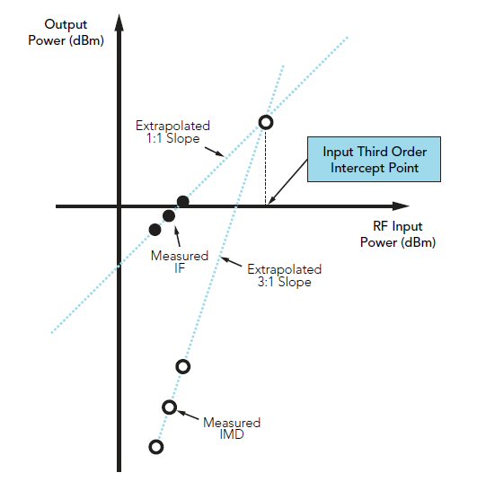
Figure 13. Graphical representation to derive input third order intercept point.
While fundamental mixing tones (i.e. m=1 and n=1) grow by a slope of 1 to 1 with input RF power, higher order RF mixing terms grow by a slope of m:1. In the case of (9), two-tone IMD grows by a slope of |m1| + |m2| to 1. Hence, interference terms in (10a) and (10b) are called third-order IMD products and grow by a slope of 3:1 as shown in Figure 13.
Graphically, the input power at which the fundamental (1:1) line and the interference (3:1) line intersect is the third order intercept point. It is notable that the TOI is an extrapolated point because the mixer would compress before the lines crossed. Nevertheless, the impact of the third-order interference products can be debilitating in many systems at RF power well below the 1 dB compression point; the higher the TOI, the better the mixer. Typical values of TOI can vary dramatically depending on the mixer type and technology. Conventional double balanced and triple balanced mixers tend to have TOI values a few dB above the recommended drive level.
Summary
The sole purpose of the microwave mixer is to provide either the sum or difference frequency of two incoming signals at the output. The goal of a mixer designer is to create a circuit that performs this frequency translation efficiently and without distortion.
References
- “Mixer Evolution, the Balanced Mixer Family Circle,” Application Note, Marki Microwave, Web. http://www.markimicrowave.com/menus/appnotes/balanced.pdf.
- F. A. Marki, “Miniature Image Reject Mixers And Their Use In Low-noise Front-ends In Conjunction With Gaas Fet Amplifiers,” 11th Asilomar Conference on Circuits, Systems and Computers, November 1977, pp. 159-162.
- F. Marki, C. and Marki, “T3 Mixer Primer,” Marki Microwave, Web. https://www.markimicrowave.com/assets/appnotes/t3_primer.pdf.
- B. C. Henderson, “Predicting Intermodulation Suppression in Double-Balanced Mixers,” Watkins-Johnson Company Technical Notes, Vol. 10, No. 4, July/August 1983.