
A summary of the features and techniques used to provide real-time, ultra-wideband, RF signal recording in a small, rugged package optimized for size, weight and power (SWaP).
Ultra-wideband RF signal recorders have allowed engineers to capture large swaths of the RF spectrum for wide bandwidth radar systems and improved SIGINT capabilities. While real-time recording of a GHz or more of RF bandwidth is commonly available in 19 in. rack-mountable systems, shrinking this capability into a form factor suitable for UAVs, aircraft pods or other confined spaces has proven challenging for the industry. Small, rugged packages must be capable of operating in extreme environments while providing similar storage capacities and data streaming throughputs as larger systems.
RF SIGNAL ACQUISITION DESIGN
The ability to record wideband RF signals in real-time is a critical requirement of radar, SIGINT, beamforming and EW systems. Wideband RF down-converters are now capable of translating a GHz of RF bandwidth to intermediate frequencies with excellent dynamic range. These signals require high performance analog-to-digital (A/D) converters (ADC) with high enough sample rates and bit resolutions to sample the entire band effectively. ADCs paired with the latest FPGA technology in an XMC form factor provide signal conversion and processing engines that can sample signals at extremely high data rates in packages suitable for a small form factor (SFF) recorder. These XMC modules serve as the recorder’s front-end interface and are used to move multiple GB/s of data through the system (see Figure 1.)
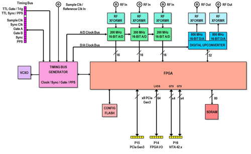
Figure 1 An XMC module includes A/Ds, D/As and an FPGA.
XMC modules are commonly available with ADCs that have maximum sample rates ranging from 200 MSPS to 6.4 GSPS. The sample rate of the ADC dictates the maximum RF signal bandwidth that can be sampled and recorded. For example, a 200 MSPS ADC with an 80 percent anti-aliasing filter can record 80 MHz of signal bandwidth, while a 6.4 GSPS ADC with a similarly shaped filter can record over 2.5 GHz of signal bandwidth. As some applications require a very wide bandwidth signal to be captured, while others require the ability to capture several channels of narrower band signals, it is important to provide an array of ADC offerings in an XMC form factor.
While the A/D sample rate is important for selecting the recorder front-end, the dynamic range of the ADC is equally as important to effectively match each application’s requirement. For an RF signal recorder, dynamic range can be described as the ratio between the largest and smallest signals that can be recorded successfully. Some signal acquisition scenarios need the ability to record very small signals in the presence of potentially very large signals, requiring an ADC with excellent dynamic range. The bit resolution of the ADC and the effective number of bits help to express dynamic range to the user. However, ADC specifications like spurious free dynamic range (SFDR) and signal to noise ratio (SNR) are even more useful. High performance 200 MSPS ADCs provide 16 bits of resolution and offer SFDRs greater than 85 dB relative to full scale (dBFS) and SNRs greater than 75 dBFS, while 6.4 GSPS ADCs provide 12 bits of resolution and offer SFDRs of about 65 dBFS and SNRs of about 55 dBFS. Typically, the higher the sample rate of the ADC, the lower the dynamic range. As before, it is important to provide a wide array of ADCs on XMC modules to cover different applications.
FPGAs coupled with ADCs on XMC modules provide an excellent digital signal processing engine for the recorder. Digital down-converting, signal detection, radar gating and acquisition time stamping are common processing capabilities often provided in standard FPGA IP designs. A well-developed set of FPGA IP modules greatly enhances the capabilities of an RF signal recorder. Digital-to-analog (D/A) converters (DAC) are often included on XMC modules to allow users to play back acquired signals or generate radar pulses. Multi-channel A/D and D/A XMC modules provide phase coherency across all channels. This is an essential capability of any real-time signal recorder as well.
Extremely small global navigation satellite system (GNNS) receivers have emerged over the last few years with support for Galileo, GPS and GLONASS systems. These small receivers support time stamping of acquired data with nanosecond precision. They provide 10 MHz reference clocks and PPS signals to the recorder’s XMC modules to allow users to capture the exact timing of gated or triggered events. GNNS receivers also allow systems to record the latitude, longitude and altitude of the recorder for logging flight paths, vehicle movements or static ground locations, if required. They often provide options for oven controlled oscillators, to enable operation across a wide range of temperatures, and accelerometers, to improve time and position accuracy during rapid acceleration. This enables operation over a wide range of environments.
OPTIMIZING THE RECORDING CAPABILITIES
Streaming data to disk in real-time at GB/s rates is achievable in large rack-mount recorders by striping data over a redundant array of inexpensive disks (RAID) of many solid-state drives (SSD). High performance RAID controllers not only provide lightning fast write speeds, they offer redundancy, protecting against the rare but disastrous disk failure that could occur during a mission. RAID controllers also use SSD features to provide data encryption and secure erase capabilities. Another feature typically seen in rack-mount recorders is front panel removable drives. An array of as many as 48 drives mounted to sleds can be inserted and removed individually from the front of the system. This allows users to remove all recorded data while allowing the recorder to remain mounted in the rack. It also allows users to maintain multiple sets of drive arrays to minimize downtime between missions.

Figure 2 A storage array packaged into a single drive pack.
The challenge of maintaining the features and performance of larger form factor recorders is facilitated by the growing solid-state storage demand driven by data centers. V-NAND flash technology enables increased solid-state drive capacity in very small package sizes. Advances in solid-state technology provide a path for shrinking the data storage array, enabling smaller and simpler designs with performance and features equal to that of far larger systems. Small drive packs, containing an array of solid-state devices, provide storage speed and capacity previously only available with many individually removable SSDs. By designing the packaging of a storage array into a drive pack (see Figure 2), the job of managing a high drive count system is replaced with the job of managing just a single drive pack, providing a tremendous ease-of-use benefit.
A single high-insertion-cycle connector designed into the drive pack provides a far more reliable mechanism for insertion and removal than standard SATA connectors typically available in rack-mount systems. Well designed drive packs are capable of holding tens of terabytes of data and are capable of GB/s storage speeds. Drive packs must be designed for easy removal to allow the recorder to remain mounted in a vehicle or aircraft.
MANAGING DIFFICULT THERMAL ENVIRONMENTS
One of the issues in reducing the package size of the data storage medium is maintaining a thermal environment that allows the drive pack to perform at its highest level. Solid-state memory controllers throttle access speeds if the thermal environment is not properly managed. This issue is a concern for all SFF recorder electronics, as well. A set of ADCs can draw 10 W or more. FPGAs often draw 25 W or more. CPUs typically draw between 35 and 90 W. High performance RAID controllers draw 15 to 25 W, and drive packs can draw 10s of Watts. While efforts can be made to minimize power consumption, heat management is one of the most critical aspects of the recorder’s design. Many RF signal recorders are installed in aircraft pods, naval ships or other outdoor environments with little or no protection. To operate in a wide array of environments, all electronics must be protected from environmental elements, such as water, humidity, sand, dust and salt fog. A hermetically sealed chassis is desirable, but brings with it the problem of removing heat from internally mounted electronics.
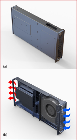
Figure 3 Plenum tubes (a) create air channels throughout the chassis, cooling the electronics mounted to their walls. The inside contains heat sinks and a fan to create air flow (b).
Custom designed heat sinks that provide conductive thermal paths to the walls of the recorder’s chassis provide some relief, but chassis walls still require sufficient air flow to be effective. Plenums can be used to create air channels throughout the chassis, providing a more efficient cooling design (see Figure 3). Custom heat sinks integrated into the plenum’s walls provide efficient cooling by allowing air to be channeled directly through all of the electronics, allowing the electronics to remain sealed from the outside environment while being adequately cooled. Integrating a fan into the plenum helps assure air flow through the heat sinks. This is ideal for systems running in hot environments like an aircraft idling on the tarmac or a military vehicle running in the dessert. What about cold environments, like an aircraft pod at high altitude or an unpressurized UAV flying in the arctic? It is equally important that the RF signal recorder is able to run at very cold temperatures.
One of the advantages of sealing all system electronics from the outside environment is self heating. This self heating process is compromised if a fan in the plenum tube is blowing cold air across heat sinks, so it is important to provide control over the fan. Integrated fan controllers monitor the environment and switch fans off to allow for self heating and then re-engage when components become hot. This balance between hot and cold is easily calibrated, providing a recording system that can operate at both temperature extremes. While these measures for thermal management help to provide an ideal environment for the recorder’s electronics, it is important to use industrial grade components whenever possible.
DESIGNING TO MILITARY SPECIFICATIONS
MIL-STD-810, "Environmental Engineering Considerations and Laboratory Tests," is a U.S. military standard for tailoring the environmental design and test limits for the conditions a system will experience during its service life. The standard also establishes test chamber methods replicating the effects of environments, rather than imitating the environments themselves. MIL-STD-810 addresses a broad range of environmental conditions: low pressure for altitude testing; exposure to high and low temperatures; temperature shock, both operating and in storage; rain, including windblown and freezing rain; humidity; fungus; salt fog for rust testing; sand and dust exposure; explosive atmosphere; leakage; acceleration; shock and transport shock; gunfire vibration and random vibration. The standard describes environmental management and engineering processes to generate confidence in the environmental worthiness and overall durability of a system design.1 While operating environments vary greatly, meeting as many criteria as possible in MIL-STD-810 is imperative to provide a reliable and robust product. Anodized metal with form-in-place gaskets allow for sealed protection against rain, humidity, fungus, salt fog and sand and dust exposure. CAD software provides simulation analysis tools to assist with thermal design and structural integrity. Well executed design techniques help assure a robust laboratory testing process.
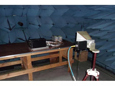
MIL-STD-461, "Electromagnetic Interference Characteristics Requirements for Equipment," is another important specification. MIL-STD-461 provides the requirements for the control of electromagnetic interference (EMI) emissions and susceptibility characteristics of electronic, electrical and electromechanical equipment and subsystems designed or procured for use by activities and agencies of the DoD.2 RF test laboratories use anechoic chambers to run a series of MIL-STD-461 tests that include radiated emissions, radiated susceptibility, conducted emissions and conducted susceptibility over a range of frequencies (see Figure 4). A radiated range up to 18 GHz and a conducted range up to 10 MHz on power leads are typical. It is important to take the appropriate design steps to ensure MIL-STD-461 compliance, since iterative independent laboratory testing is expensive. Design techniques used to control EMI include the use of RF emission filters and RF gaskets to prevent radiated electromagnetic emission and susceptibility. Additionally, an in-line EMI power filter designed for the internal power supply can be used to protect against conducted emissions and susceptibility.
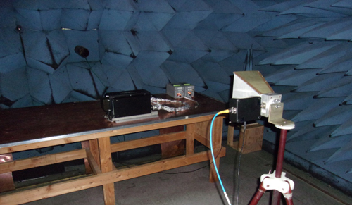
Figure 4 Testing an RF signal recorder to MIL-STD-461.
SWaP
The term SWaP has become a common buzzword to describe the requirement for electronic systems that are small in size, weight and power consumption. Why the obsession with SWaP? It has to do with the need for sophisticated electronics small enough for unmanned vehicles and for reducing the burden on infantrymen, who, in today’s combat environment, must carry computers, displays, communications devices and sensors, in addition to their combat gear. Overall, today’s focus on small, lightweight electronic systems that consume little power has to do with bringing as much capability to the forward edge of battle as possible.3 Having focused on reducing the size of the RF signal recorder, designing for weight and power reduction require additional strategies. The good news is that reducing weight also reduces power consumption and heat dissipation. Removal of heat from the system’s electronics via conduction requires conductive materials such as aluminum or copper. While copper is more effective for conducting heat, its density is far greater than aluminum, adding undesirable weight to the recorder. Designing for reduced weight requires minimizing power consumption and using lightweight materials such as aluminum with efficient thermal paths to cooling channels. High speed recording systems often do not require a tremendous amount of processing power. Since hardware direct memory access controllers are used to move data to disk, processors are often used to simply "manage" the data flow. Intel’s latest i7 processors are offered in versions with lower clock rates and power consumption. An eighth generation i7, clocking at 2.4 GHz, limits power consumption to 35 W and can be configured to draw as little as 25 W. Efficient FPGA designs allow digital signal processing to reside in smaller, more efficient FPGAs. Xilinx’s Kintex Ultrascale family offers excellent performance with significant power reduction, compared to previous generations. Component selection and an efficient design help to control the power consumption and dissipation of the recorder, enabling the use of less material for heat sinking and reducing package weight.
EASE-OF-USE
While SWaP is important, it is equally important that the system be designed for ease-of-use - both hardware and software. Designing a system in a standard form factor helps simplify installation by providing familiar mounting mechanisms in a common and proven footprint. ARINC 404 is an aeronautical standard that specifies mechanical dimensions of line replaceable units and their racking systems in aircraft. ARINC 404 specifies dimensions for several sizes of air transport racks, providing a choice of standard footprints for the signal recorder. It is important to design a system that can be permanently installed in an aircraft or vehicle and still provide user accessibility. Replaceable modular components like fans, drives and other parts of non-volatile memory within the recorder allow easy service and sanitization of classified or sensitive data. All removable components should be accessible via the system front panel using captive hardware, without the requirement for special tools. Software should include a user-friendly application programming interface (API) to control the system, as well as a suite of RF signal analysis tools to instantly analyze recorded data. RF signal recorders typically provide a Gb Ethernet interface for control of the unit from an external computer. This interface can also be used to stream data to allow users to monitor RF signals prior to, during and after a recording. It is essential to remotely control the recorder to enable operation in unmanned environments. This often requires a user-generated custom control interface. It is also desirable to provide a fully functional graphical user interface (GUI) to allow operation out of the box. The GUI should run remotely, as well.
CONCLUSION
RF signal recording is an essential component of any radar, SIGINT, beamforming or EW system. A well designed system provides RF signal acquisition hardware that is small, lightweight, low-power and capable of operating over a wide range of operating environments. Features such as drive packs and other serviceable modular components allow ease of installation and maintenance in tight spaces and enable ultra-wideband RF signal recording in places and environments never before possible.
References
- "MIL-STD-810," Wikipedia, en.wikipedia.org/wiki/MIL-STD-810.
- "MIL-STD-461 Testing," NTS, www.nts.com/industries/defense/mil-standards/mil-std-461-testing/.
- J. Keller, "SWaP: How Size, Weight, and Power are Transforming the Military Electronics Industry," June 2013, www.militaryaerospace.com/articles/print/volume-24/issue-6/news/trends/swap--how-size--weight--and-power-are-transforming-the-military-.html.