
Technologies like terabit optical data communications, next-generation digital bus standards, high speed I/O and new wireless standards are demanding higher bandwidth and more accurate measurements in multi-channel test systems. Similarly, emerging mmWave applications are demanding wider bandwidths. For example, 802.11ay uses about 4 GHz of bandwidth at 60 GHz. High signal integrity is needed for measurements such as error vector magnitude (EVM), especially over multi-GHz signal bandwidths with high-order modulation.
To address these needs, Keysight has designed a 110 GHz oscilloscope with custom ASICs to achieve more signal integrity than any other oscilloscope in its class. The technology has been leveraged and optimized down to 13 GHz models, providing extreme signal integrity in a wide range of bandwidth options, enabling high speed digital design and wireless. Keysight’s Infiniium UXR-Series oscilloscopes are the first oscilloscopes to achieve greater than 40 GHz bandwidth without frequency interleaving, which adds noise and distortion to the signal being tested.
JOURNEY OF A SIGNAL
To understand the technology within Keysight’s new oscilloscopes, follow the signal flow through a UXR (see Figure 1). The signal enters through the channel, a challenge when developing a high bandwidth oscilloscope, as reflections in the channel cause measurement inaccuracy. The 33 GHz and below models use robust 3.5 mm connectors (only accurate below 40 GHz), Keysight’s traditional AutoProbe II interface to support traditional SMA connections and Infiniium probes that may already be on the lab bench. The 40 to 70 GHz models use 1.85 mm connector technology, which is a little more delicate but extends the bandwidth. To support 80 GHz and above, Keysight uses 1 mm connectors, the industry standard for mmWave technology to 110 GHz. While these connectors are traditionally more fragile like all 1 mm connectors, they require adaptors to connect to traditional probes, but users testing at these frequencies will likely connect cables directly to the 1 mm input to maintain signal integrity, rather than using hand-held probes.
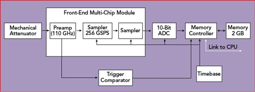
Figure 1 Simplified block diagram of the UXR oscilloscope.
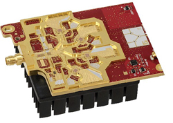
Figure 2 The 110 GHz front-end module.
From the front-end connector, the signal flows to a mechanical attenuator and then into the preamplifier, the first component of the front-end module. While this may sound simple, it is one of the key distinctions between UXR oscilloscopes and other high bandwidth oscilloscopes. The front-end module consists of a proprietary Keysight InP chipset protected from noise and interference with a Faraday cage (see Figure 2), custom designed to handle 110 GHz signals while keeping noise to a minimum. This is a key distinction, because the hardware can support the full bandwidth of the oscilloscope. Other high bandwidth oscilloscopes must use frequency interleaving to achieve the full bandwidth because the IC technology within the oscilloscopes is limited. Frequency interleaving can double—even triple—an oscilloscope’s bandwidth beyond the raw capability of the chipset. The trade-off is additional circuitry, adding significant noise and distortion which are amplified by the preamp. With interleaving, digital signal processing stitches the signal components back together, which may add more noise to the signal. This all happens in the front-end of the oscilloscope before data acquisition. Using a preamp with a frequency range to 110 GHz without attenuation, the UXR foregoes frequency interleaving, preserving the signal under test. One of the trade-offs to designing hardware to support higher bandwidth without frequency interleaving is time-to-market. However, the improvement in performance is well worth the design effort.
After the attenuator and the preamp, the signal flows to a 256 GSPS sampler (also designed uniquely for the UXR using InP) and a trigger comparator. The 256 GSPS high speed sampler “slows” the signal for the rest of the system, using a process called time interleaving. Unlike frequency interleaving, time interleaving is carefully controlled with the oscillator board. Signal acquisition uses an array of 10-bit analog-to-digital converters (ADC), with each ADC operating at 64 GSPS. 10-bit ADCs provide 4× the vertical resolution of 8-bit ADCs. After being converted to digital, the signal is sent to Keysight’s new memory controller reading and writing to a modern 2.5D memory storage device with 2 GB of deep memory. The trigger comparator sends trigger information to the memory controller, which enables filtering, de-embedding, triggering and other advanced hardware features. It even has a bus for plotting the waveform, reducing the work done in the FPGA to speed the performance of the oscilloscope. The memory controller sends this data to the FPGA, which communicates to the CPU over PCI Express to display the signal and measurements on the screen of the oscilloscope. Each 110 GHz channel has its own acquisition board, ensuring the full bandwidth and memory depth on each channel.
This oscilloscope design has enabled new industry “bests.” The UXR provides:
- Four full bandwidth channels with up to 110 GHz of bandwidth.
- As low as 210 μV rms noise at 10 mV/division.
- Only 25 fs rms of intrinsic jitter at 1 μs/div.
- Less than an additional 10 fs rms of inter-channel intrinsic jitter.
- Up to 6.8 effective bits.
WHY DOES THIS MATTER?
For emerging mmWave applications to 110 GHz, high performance digital oscilloscope technology offers an additional tool to gain insight when analyzing wideband mmWave signals. Directly digitizing mmWave signals, then post-processing them with application software enable direct measurement of wideband mmWave signals, complementing the traditional approach using an external down-converter with a lower bandwidth oscilloscope. The UXR’s accuracy—up to 6.8 effective bits—enables wideband EVM measurements of higher-order modulation signals, such as 802.11ay.
As anyone in the high speed digital industry knows, test margins are decreasing as new generations of technology become the standard. Design cycles are shorter, and compliance is more difficult as the limits of existing hardware are reached. Previously, there was so much time between bit transfers that set up and rise time tests were only required to pass specification. Now, passing compliance requires pre- and post-channel equalization as well as strict mask test validation. Millivolts of noise can make the difference between passing or failing. The UXR’s signal integrity reduces the risk of failing from excessive oscilloscope noise and jitter. With a noise floor as low as 210 μVrms at 10 mV/division and only 25 fs of intrinsic jitter, signal eyes will be wider, leading to more confidence passing compliance tests.
In terabit and optical research, next-generation technology breakthroughs have been prohibited by limited test equipment. Higher modulation standards require measurement systems with extreme signal integrity, high bandwidth and multiple channels to decipher complete coherent receiver designs. Daisy chained single channel instruments can be too costly and highly inaccurate. Inter-channel jitter between daisy chained measurement devices can impede the ability to clearly view signals. Four high bandwidth channels with only femptoseconds of inter-channel intrinsic jitter enable optical measurements not previously possible.
The UXR was designed piece by piece, with the intention to enable research in various applications with new industry-best specifications. Keysight’s new technology blocks enable the UXR to revert to traditional, clean oscilloscope design practices without frequency interleaving, increasing the signal fidelity in every category.
Keysight Technologies Inc. Santa Rosa, Calif.
www.keysight.com/find/UXR