
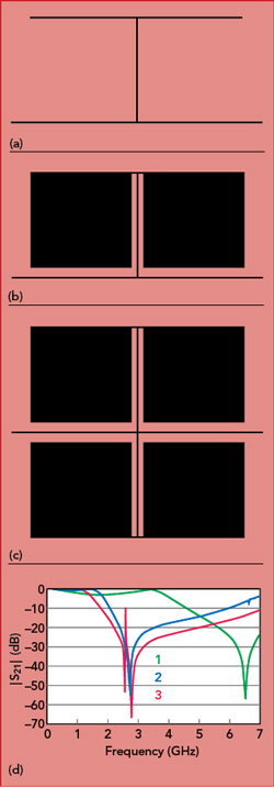
Figure 1 Resonator layout: 1 (a), 2 (b), 3 (c) and simulated |S21| (d).
A microstrip lowpass filter (LPF) with very small dimensions and an extremely wide rejection band has a cutoff frequency (fc) of 1.89 GHz and suppresses the second to 34th harmonics (2.38 to 65 GHz) by greater than than 24 dB. The filter’s simple topology consists of a symmetrical modified T-shaped resonator, a symmetrical modified flag-shaped (SMF) resonator and open-circuited stubs as suppression elements to achieve the ultra-wide stopband. Passband ripple is less than 0.15 dB. The overall dimensions are only 0.153λg × 0.065λg, where λg is the guided wavelength at fc. The filter has a high figure of merit (FOM) of 32.465 and passband return loss better than 14.8 dB.
Microstrip LPFs with desirable properties—such as a wide stopband with high rejection and small size—are widely utilized in telecommunications systems to reject undesirable out-of-band peaks.1-2 Raphika et al. reported on an LPF using an improved T-shaped resonator.3 To increase the stopband width of this filter, four stepped-impedance stubs were used. Nevertheless, harmonic suppression was weak. Karimi et al.4 developed a microstrip LPF with a suitable suppression level using T- and U-shaped resonators. To extend the stopband, radial stubs were added, even though this structure inherently has a narrow stopband and occupies a large area. Zhang and Li5 introduced a dual-layer LPF, with large dimensions and a narrow stopband. The structures reported by Verma et al.6 are simple, but they are large with narrow stopbands, as well. Kufa and Raida7 introduced a conventional LPF using an open-circuited stub and an embedded, defected ground to reduce circuit dimensions; however, it had a slow transition band, enormous size and weak harmonic suppression. Several LPFs with high return loss in the passband were studied,8-10 but they were challenged by wide transition bands and narrow stopbands. Attempts to increase the stopband width with defected ground planes have had limited success, and these filters were also large.11-16 Hayati et al.17 reported on a compact LPF with high return loss in the passband, using hexangular-shaped resonators. To have a high suppression level, rectangular stubs were utilized. However, this structure only suppressed up to the seventh harmonic. A symmetrical LPF by Mirzaee and Virdee18 was limited by a gradual cutoff and large dimensions. The LPF by Liu et al.19 suffered from a slow transition band and a narrow rejection band. Recently, a novel LPF with high return loss using symmetrical topology was presented.20
In this work, a novel LPF with high out-of-band suppression uses a symmetrical modified T-shaped resonator. Compact, an extremely wide stopband from 2.38 to 65 GHz, high return loss (14.8 dB) in the passband and a simple topology are beneficial properties.
FILTER DESIGN
The design sequence of the T-shaped resonator is shown in Figure 1, including the layouts of resonator 1, resonator 2 and resonator 3 and their simulated |S21| responses. Resonator 1 is composed of two rectangular open stubs and one high impedance stub connected to a narrow transmission line. Resonator 1 has a slow transition band, with high passband ripple. With low impedance stubs added (resonator 2), a relatively sharp transition band is achieved. For a sharper transition band and negligible passband ripple, a symmetrical topology (resonator 3) is used.
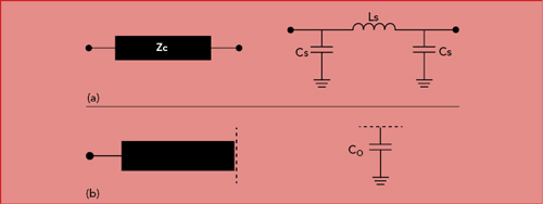
Figure 2 Layout and L-C model of high-low impedance lossless line (a) and open-circuited stub (b).
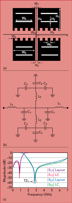
Figure 3 Symmetrical modified T-shaped resonator layout (a), L-C model (b) and simulated responses (c).
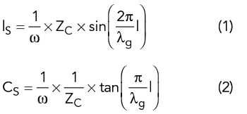
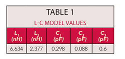
The inductance and capacitance of a high-low impedance lossless line (see Figure 2a) are computed using Equations 1 and 2, as is the capacitance of an open-circuited stub (see Figure 2b).2 The inductance of the stub is negligible.
To develop the stopband, a symmetrical modified T-shaped resonator is used, as depicted in Figure 3a, with the L-C model of the resonator shown in Figure 3b. The inductances and capacitances of the transmission lines are designated as L1 and C1, respectively. L2 and C2 are the inductances and capacitances of the high impedance stubs, respectively. C3 are the open-circuited low impedance stub capacitances. The inductances of the low impedance stubs are negligible. The L-C model values are found in Table 1. EM and L-C simulation results (see Figure 3c) show a transmission zero (TZ1) at 2.83 GHz. The LPF is simulated with Advance Design System (ADS) software, assuming an RT-Duroid 5880 substrate (εr = 2.2, h = 0.381 mm and loss tangent = 0.0009). The physical dimensions of the resonator (in mm) are: H1 = 3.3, H2 = 8.75, H3 = 0.42, H4 = 3.55, H5 = 0.137, W1 = 0.1, W2 = 3.43, W3 = 0.1, W4 = 2.46, W5 = 0.38 and W6 = 0.4. TZ1 is calculated using the L-C model of Figure 3b.
The ABCD matrix is defined for a two port network1 as
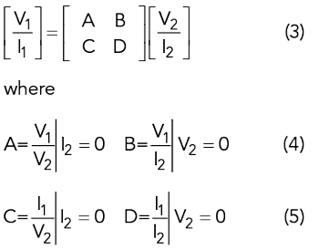
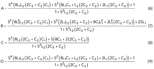
According to Equations 4 and 5, the ABCD parameters of the proposed resonator are obtained from
From the ABCD parameters, S21 is1
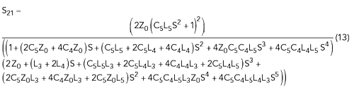
![]()
The S21 of the proposed resonator is
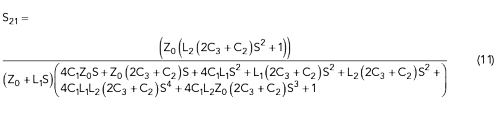
The transmission zero (TZ1) is extracted from Equation 11
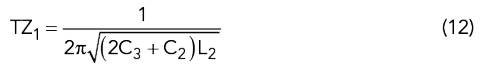
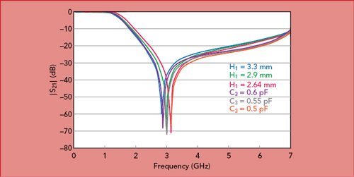
Figure 4 Simulated TZ1 of the symmetrical modified T-shaped resonator vs. H1 and C3.
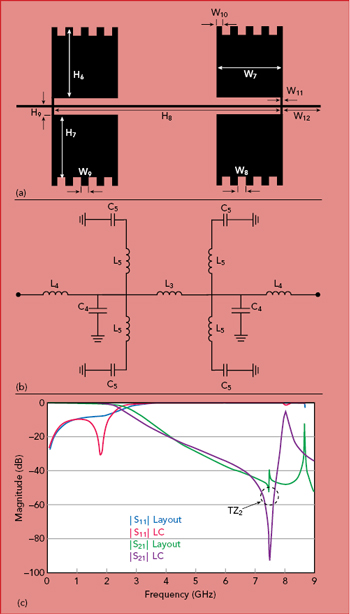
Figure 5 Example showing contributions from each of four formation to each transmitters to each of four receivers.
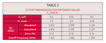
According to Equation 12, TZ1 is a function of C3, where C3 is the capacitance of H1. By reducing the length of H1, TZ1 and the cutoff frequency move higher in frequency (see Figure 4). As a result, the cutoff frequency is adjusted by TZ1. For a low cutoff frequency, TZ1 is tuned to 2.872 GHz. Cutoff frequencies for different values of C3 and H1 are summarized in Table 2.
Symmetrical Modified Flag-Shaped Resonator
Figure 5a shows the layout of the SMF resonator, and the L-C model is shown in Figure 5b. Inductances and capacitances of the transmission line are L3, L4 and C4, respectively. L5 is the sum of the high impedance and low impedance stub inductances. C5 is the open-circuited low impedance stub capacitance. The capacitances of the high impedance stubs are negligible. The L-C model values are presented in Table 3. EM and L-C simulation results are shown in Figure 5c and agree with the model. The SMF resonator creates a transmission zero (TZ2) at 7.6 GHz. The physical dimensions of this structure (in mm) are: W7 = 3, W8 = 0.29, W9 = 0.41, W10 = 0.25, W11 = 0.1, W12 = 3.25, H6 = 3.24, H7 = 2.97, H8 =13.61 and H9 = 0.37.
From Equation 10, the S21 of the SMF resonator is calculated as
TZ2 is extracted from Equation 13
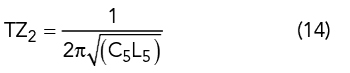
According to Equation 14, TZ2 is tuned by L5 (see Figure 6).
To have a wide stopband, the symmetrical modified T-shaped resonator and SMF resonator are combined, as shown in Figure 7a. The EM simulation of the combined resonator is shown in Figure 7b. This structure has two transmission zeros (TZ1 and TZ2) at 2.7 and 6.6 GHz, respectively.
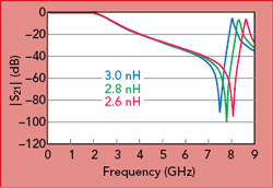
Figure 6 Simulated |S21| of the SMF resonator vs. L5.
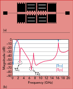
Figure 7 Layout (a) and simulated responses (b) of the combined resonator.