
A Doherty power amplifier (DPA) uses ferroelectric ceramics for linearity improvement. The conventional λ/4 transmission line is replaced by ferroelectric ceramics for 90 degree phase delay compensation. The phase of the peak amplifier input can be changed by modifying the voltage on the barium strontium titanate (BST) ferroelectrics to suppress AM to PM distortion. Compared with a conventional DPA, third-order intermodulation distortion (IMD3) is reduced by 16 dB.
Power amplifier (PA) linearity over a wide dynamic rang e is a key performance parameter in modern wireless communication systems employing complex digital modulation. DPAs have demonstrated high efficiencies over wide output power ranges, but DPA linearity cannot satisfy the stringent requirements of modern wireless communication systems. Linearization enhancement techniques, such as the use of wideband phase inverters, composite right/ left-handed transmission lines (CRLH-TL) and asymmetrical DPA structures, have been proposed;1-4 however, phase cannot be modified to improve linearity during the debugging process.
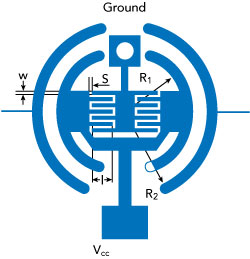
Figure 1 Ferroelectric ceramic structure.
Ferroelectric varactors have been used as tunable elements in CRLH phase shifter applications,5 and phased array antennas have employed tunable phase shifters based on ferroelectric ceramics, as well.6 In this work, ferroelectric ceramics replace a conventional DPA’s λ/4 transmission line to achieve a 90 degree phase shift. The result is improved linearity without affecting power-added efficiency (PAE).
HIGH LINEARITY DPA DESIGN
The BST ferroelectric ceramic resonant cell contains a series of interdigital capacitors (IDC) and a grounded stub line as a shunt inductor (see Figure 1). IDCs with the following dimensions are used in the series branch: length l = 115 μm, finger width w = 46μm and gap widths=23μm. R1 and R2 are 1.2 and 3.5 mm, respectively. The BST thick film has a height of 2 μm and is screen printed and sintered on an Al2O3 substrate with a height of 620 μm and εr = 10.1. The relative permittivity of the BST (εr = 175).
The circuit architecture is shown in Figure 2. The peak class C PA signal through the BST ferroelectric ceramic resonant cell is combined with the main class AB amplifier signal at the DPA output. As a result, a 90 degree phase delay, a tunable input capacitance of the peak amplifier FET and a tun- able phase of the peak amplifier in- put are achieved at the same time.
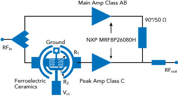
Figure 2 DPA schematic.
Linearity Improvement
At high-power levels, when the peak amplifier is turned on, contributions to IMD3 are from both the main and peak amplifier; however, the peak amplifier dominates be- cause it is operated class C. AM to PM distortion in the peak amplifier is a key factor, traceable to the signal-level dependence of the transistor model elements. Of these elements, the FET input capacitance is the biggest contributor.
The nonlinear characteristic of the peak amplifier can be expressed as1,7
i(t)=gm1V + gm2V2 + gm3>V3 + ... (1)
where i(t) and V are the current and voltage of the drain electrode in the peak amplifier, and gmn are the transfer functions. The third-order intermodulation product (IM3) is expressed as
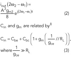
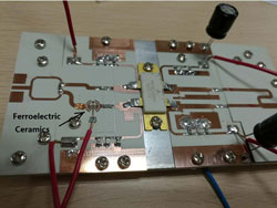
Figure 3 Assembled DPA.
where RL is the load resistance, Cin is the total input capacitance, Cbe and Cbc are base-emitter and base-collector capacitors, respectively, and gce is the collector-emitter transfer function.
While the phase of the peak amplifier input is controlled by modifying the voltage of the BST, the input capacitance is also modified to decrease AM to PM distortion; Cbe is affected by the ferroelectric ceramics, according to Equation 3, so Cin is modified as well. The values of gm for the main amplifier and peak amplifier are of opposite phase and with modification to Cin of the peak amplifier by the ferroelectric ceramics, gm of the peak amplifier is the same magnitude as that of the main amplifier. This reduces overall IMD3. Linearity of the DPA is therefore improved compared with a conventional DPA.
IMPLEMENTATION AND EXPERIMENTAL RESULTS
The DPA is fabricated on Rogers 4350 substrate (see Figure 3). The bias voltage to the BST ferroelectric ceramic is 45 V for a 90 degree phase shift. An NXP MRF8P26080H LDMOS power transistor is used for both the main and peak amplifiers. VDS of the main amplifier and peak amplifier are both 28 V, while VGS of main amplifier and peak amplifier are 2.65 and 2.28 V, respectively. The operating frequency range is from 2570 to 2620 MHz.
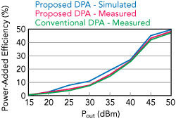
Figure 4 Simulated and measured power- added efficiency of this DPA vs. measured performance of a conventional DPA.
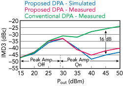
Figure 5 Simulated and measured IMD3 of this DPA vs. measured performance of a conventional DPA.
Simulated and measured PAE for this DPA compared to the measured PAE for a conventional DPA at 2.6 GHz are shown in Figure 4. The DPA described in this work has a slightly higher PAE compared with the conventional DPA, with a maximum PAE of 46.2 percent. Figure 5 shows the simulated and measured IMD3 for this DPA compared to the measured IMD3 for the conventional DPA, using a two-tone signal at a center frequency of 2.6 GHz with 5 MHz tone spacing. IMD3 of this DPA is considerably improved com- pared to the conventional DPA. At a low-power level, they are almost the same, because the peak amplifier is turned off. When the peak amplifier turns on, however, IMD3 is improved by as much as 16 dB.
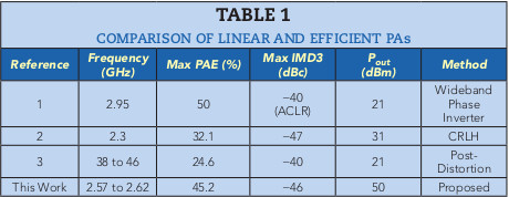
Table 1 compares this work with recently published PAs having high linearity and efficiency.
CONCLUSION
A DPA suppresses AM to PM distortion of the peak amplifier. This is done by modifying the voltage of a BST ferroelectric ceramic resonant cell at the input. Comparisons with a conventional DPA and recently published works show the potential for improved linearity with the comparable efficiency.
References
- S. W. Y. Mung and W. S. Chan, “Wide- band Phase Inverter Integrated in Doherty Power Amplifier for Linearity Improvement,” Electronics Letters, Vol. 51, No. 10, May 2015, pp. 771–773.
- S.H. Ji, S.K. Eun, C.S. Cho, J.W. Lee and J. Kim, Linearity Improved Doherty Power Amplifier Using Composite Right/Left-Handed Transmission Lines, IEEE Microwave and Wireless Components Letters, Vol. 18, No. 8, August 2008, pp. 533–535.
- J. H. Tsai and T. W. Huang, A 38-46 GHz MMIC Doherty Power Amplifier Using Post-Distortion Linearization,” IEEE Microwave and Wireless Components Letters, Vol. 17, No. 5, April 2007, pp. 388–390.
- J. Kim, B. Fehri, S. Boumaiza and J. Wood, Power Efficiency and Linearity Enhancement Using Optimized Asymmetrical Doherty Power Amplifier, IEEE Transactions on Microwave Theory and Techniques, Vol. 59, No. 2, February 2011, pp. 425–434.
- D. Kuylestierna, A. Vorobiev, P. Linner and S. Gevorgian, Composite Right/ Left Handed Transmission Line Phase Shifter Using Ferroelectric Varactors, IEEE Microwave and Wireless Components Letters, Vol. 16, No. 4, April 2006, pp. 167–169.
- M. Sazegar, Y. Zheng, H. Maune, C. Damm, X. Zhou, J. Binder and R. Jakoby, Low-Cost Phased-Array Antenna Using Compact Tunable Phase Shifters Based on Ferroelectric Ceramics, IEEE Transactions on Microwave Theory and Techniques, Vol. 59, No. 5, May 2011, pp. 1265–1273.
- J.H. Kim, C.S. Cho, J.W. Leeand J. Kim, Linearity Improvement of Class-E Doherty Amplifier Using gm3 Cancellation, Electronics Letters, Vol. 44, No. 5, February 2008, pp. 359–360.
- Y. Cho, D. Kang, J. Kim, K. Moon, B. Park and B. Kim, Linear Doherty Power Amplifier with an Enhanced Back-off Efficiency Mode for Handset Applications, IEEE Transactions on Microwave Theory and Techniques, Vol. 62, No. 3, March 2014, pp. 567–578.