
Time-Interleaved ADCs
These ADC architectures implement a range of “m” parallel “sub-ADCs” and each sub-ADC samples the incoming signal at every m’th cycle of the system clock. This arrangement causes the sample rate to be increased by a factor of ‘m’ compared to the sampling rate capability of each individual sub-ADC. Time-interleaved ADCs are therefore usually very fast indeed–enabling GHz operation.
In a TI ADC each consecutive “sub-ADC” is clocked by a successively delayed clock waveform.
Phased-Array Antennas and Beamforming
Most “phased-array” antennas comprise flat-panel or “patch” arrays which are often based on microstrip transmission line configurations. Otherwise various conducting patch structures are frequently implemented and complete, packaged versions of such antennas take on physical dimensions very similar to those of commercial indoor Wi-Fi hubs.
These types of antennas can provide gains up to about 20 dBi and they are generally installed onto indoor walls. A center frequency of 2.4 or 2.7 GHz usually applies to such antennas and a straightforward flexible coaxial provides the output line carrying the intermediate-frequency signal.
Beamforming represents a major requirement for many types of systems implementing phased-array antennas (5G is an important example). Massive input/massive output (MIMO) systems are being put forward as potential candidates for several new types of communications systems. Beamforming–both analog and digital–forms a vital part of this approach principally applicable to radars or to prospective 5G systems. Hybrid beamforming is a combination of analog and digital beamforming and the principle is indicated in Figure 4.
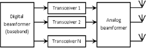
Figure 4 Architecture of a hybrid beamformer.
With the hybrid beamformer system adaptive weighting is available in both analog and digital domains. As a result there is optimization between both coverage and capacity.
Multi-element MIMO arrays are feasible with element counts up to at least 64. Operation to at least 30 GHz has been demonstrated.
In manufacturing terms the 3D printing of flat-panel antennas also represents an important advancement.
Low-Phase Noise Sources
It has long been recognised that phase noise represents a major issue for frequency sources such as oscillators and frequency synthesizers. More recently it has also been appreciated that this phenomenon is important for low-noise amplifiers. Phase noise (especially close-in to the carrier) represents a very important quantity in amplifiers designed for sensitive requirements. For a fundamental crystal-stabilized oscillator the phase noise even as close as 100 Hz from the carrier (typically 100 or 140 MHz) can be as low as -144 dBc. However the phase noise for most other types of frequency source is more like -70 dBc, even at frequencies much further removed from the carrier, e.g., 10 or even 100 kHz away.
MEMS (micro-electro-mechanical systems) are becoming popular for the frequency stabilization of low-noise high-frequency clock sources. Gronefeld4 has reported ultra-low phase noise dielectric resonator oscillators (DRO) using X-ray-based free-electron lasers.
Time-Interleaved ADCs (TI ADCs)
These ADC architectures implement a range of “m” parallel “sub-ADCs” and each sub-ADC samples the incoming signal at every m’th cycle of the system clock. This arrangement causes the sample rate to be increased by a factor of "m" compared to the sampling rate capability of each individual sub-ADC. Time-interleaved ADCs are therefore usually very fast indeed.1
In a practical system physical differences between the sub-ADCs degrade the overall performance but provided the system is integrated (RFIC) such differences are generally negligible. Delays are of the order of ns. Equivalent numbers of bits (ENOB) are typically in the range 4 to 6 and TI ADCs can operate at frequencies well into the GHz range.
For further details concerning time-interleaved ADCs the references5-7 are recommended.