
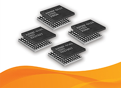
Anokiwave has introduced a family of four, single-channel, Ku- and Ka-Band silicon ICs offering complete transmit/receive functionality, including active gain and phase control. The architecture enables the ICs to be used as traditional gain blocks with the addition of gain and phase control—hence the name “Intelligent Gain Blocks” (IGB). This new family enables designers to use the same IC for multiple functions across the RF signal chain, achieving equivalent or better performance than traditional, discrete GaAs ICs and with increased software control. The versatile IC family can be used in a wide range of applications, including SATCOM, radar, 5G and sensing. The integration and small size allow the ICs to be used in radar or communications phased arrays, as well as replacing discrete, single function blocks.
Two of the four ICs in the IGB family cover 10.5 to 16 GHz (Ku-Band), and two cover 26 to 30 GHz (Ka-Band). Each IC contains a PA, LNA, 6-bit gain and phase control; two of the ICs—one in each band—have an integrated T/R switch at the front-end (see Figure 1a). The two others eliminate the T/R front-end switch (see Figure 1b), offering users the option to eliminate the switch loss. The performance of the IGB family is summarized in Table 1.
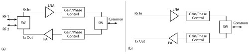
Figure 1 Functional block diagram of the Ku- and Ka-Band IGBs with (a) and without (b) the T/R switch at the LNA input and PA output.
Consider a few of the ways the IGBs can be used:
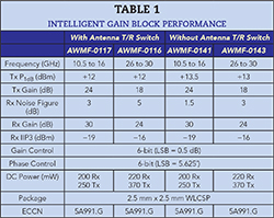
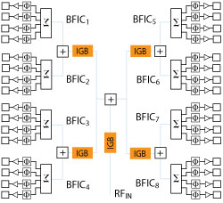
Figure 2 The IGBs can be used to independently compensate amplitude and phase variations within the signal distribution section of a phased array.
Core distribution ICs in active arrays: In 5G and SATCOM active antenna arrays, the challenge of compensating the array is unique because the RF input is split and combined multiple times to feed the beamformer ICs. Each split and combination causes gain and phase mismatch. While the beamformer ICs have built in gain and phase adjustment, they are typically designed to just steer the antenna beam. The IGBs can be used to provide the required gain and phase compensation within the array where the RF signal is distributed or combined (see Figure 2).
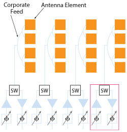
Figure 3 In a column-fed phased array, a single IGB can control the amplitude and phase for a column, replacing multiple discrete functions.
Integrated blocks for alternate 5G architectures: For 5G architectures using a traditional column-fed architecture, the single-channel IGB can be used to replace the front-end control section with just a single IC for each column, as shown in Figure 3. An IGB in this architecture simplifies the overall design, reducing size, parts count and the bill of materials cost compared to discrete parts.
Single function blocks: The IGB integrates multiple RF functions within the same silicon IC; however, each can be used as a discrete single function. The same IC can be used as a discrete LNA, with or without a front-end switch; a driver amplifier, with or without the switch; variable gain amplifier (VGA); phase modulator or full vector modulator. Fabricated with advanced silicon technology, the IGBs meet or exceed the performance of many traditional GaAs products.
Used as an LNA, the IGBs provide 1.5 dB noise figure at Ku-Band and 2.5 dB at Ka-Band, consuming only 200 mW DC at Ku-Band and 220 mW at Ka-Band. With the added SPDT input switch, the noise figure increases to 3 dB at Ku-Band and 5 dB at Ka-Band. The DC power consumption remains the same.
Used as a driver amplifier, the IGBs provide high gain and medium output power: 13.5 dBm at Ku-Band and 13 dBm at Ka-Band at 1 dB compression, with gains of 25 and 19 dB, respectively. For system architectures requiring the SPDT switch, the output power at 1 dB compression is 12 dBm in both bands, with 24 dB gain at Ku-Band and 18 dB at Ka-Band. The ICs consume 250 mW at Ku-Band and 370 mW at Ka-Band.
As a variable gain amplifier, the ICs provide 25 dB maximum gain at Ku-Band and 19 dB at Ka-Band, and 31.5 dB dynamic gain control. The 6-bit design provides an LSB of 0.5 dB with a typical RMS amplitude error of 0.5 dB. The 1 dB compression point is 13.5 dBm at Ku-Band and 13 dBm at Ka-Band.
As a phase modulator, the IGBs have 6-bit phase resolution, i.e., an LSB of 5.625 degrees, with a typical RMS phase error of 5 degrees. The gain is 25 dB for the Ku-Band design and 19 dB for the Ka-Band version, with 1 dB compression points of 13.5 and 13 dBm at Ku- and Ka-Band, respectively.
Used as a vector modulator, the ICs have maximum gains of 25 dB at Ku-Band and 19 dB at Ka-Band, with 1 dB compression points of 13.5 and 13 dBm, respectively. The gain control range and resolution are the same as the VGA: 31.5 dB with 0.5 dB step size and 0.5 dB RMS error. Similarly, the 6-bit phase control has an RMS phase error of 5 degrees.
Integrated block: Taking advantage of the integration, the IGB can replace multiple RF functions with a single, small IC. As shown in Figure 4, one IGB replaces seven, separate GaAs components with a single 2.5 mm x 2.5 mm IC, without compromising performance.
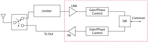
Figure 4 The IGB integrates seven functions in a single, 2.5 mm x 2.5 mm IC.
Anokiwave’s new IGBs will redefine Ku- and Ka-Band designs. They are available in developer kits, small quantities for development programs and volume production quantities.
Anokiwave
San Diego, Calif.
www.anokiwave.com