
Hybrid-active load-pull overcomes the challenges in mmWave power amplifier design by removing the uncertainty of unclosed contours to enable designing for peak performance.
Fifth-generation mobile represents the next evolution in wireless communications. With an emphasis on connectivity, 5G is expected to bring together data, voice, video, IoT, connected cars, smart homes, smart cities, augmented reality and industrial automation. 5G will achieve this aggressive goal by deploying technologies over multiple frequency bands, from low MHz to high GHz. Research in the 450 MHz to 6 GHz bands is targeting long-range communication and in the 28 to 30 and 37 to 39 GHz bands for high data rates. While posing unique challenges, the mmWave bands promise to bring many advantages, including larger bandwidth, greater capacity, increased security and longer battery life.
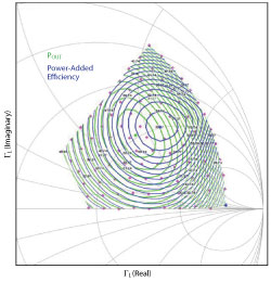
Figure 1 Output power and power-added efficiency load-pull contours.
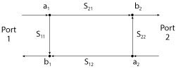
Figure 2 Two-port S-parameter model of a DUT.
A critical enabler in the 5G infrastructure is the power amplifier (PA), which must be properly designed for optimum performance, i.e., maximizing power and efficiency while maintaining appropriate linearity. A useful design tool for maximizing performance is load-pull.
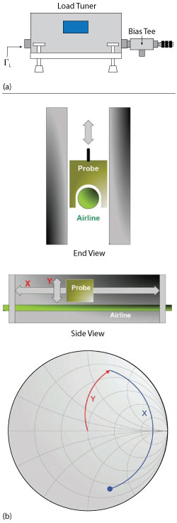
Figure 3 Passive tuner for performing load-pull measurements (a) comprising a passive slide screw tuner and probe (b).
Load-pull Techniques
Load-pull is the process of changing the load impedance presented to a device under test (DUT), commonly a transistor, to measure its performance characteristics under varying large-signal conditions. The impedance is systematically changed while parameters such as output power, gain and efficiency are measured or calculated. Contours representing fixed performance values (e.g., x dBm output power or y percent efficiency) are then plotted to visualize the point of maximum performance, the rate at which the performance changes and trade-offs between various parameters (see Figure 1).
But how does load-pull work? First, consider a DUT as a two-port network (see Figure 2). A signal a1 is injected into port 1 of the DUT. A portion of the signal is delivered to the DUT while another portion is reflected as b1, due to the mismatch between the input impedance of the DUT and the source impedance of the input network. A modified signal b2 exits port 2 of the DUT and is delivered to the load, while a portion of it is reflected back as a2, due to the mismatch between the output impedance of the DUT and the load impedance of the output network. The magnitude and phase of that reflection, represented as ΓL, is
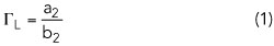
Load-pull changes the magnitude and phase of ΓL by changing the reflected signal a2. Any load impedance, which can be calculated as

can be presented to the DUT as long as the signal a2 can be achieved. There are two common methodologies to vary the impedance presented to the DUT: passive load-pull and active load-pull.
Passive Load-Pull
Passive load-pull uses mechanical impedance tuners to change the magnitude and phase of the reflected signal a2 and vary the impedance presented to the DUT (see Figure 3a). The magnitude and phase of the load impedance are adjusted by varying the position of a probe (or slug) in both x and y axes along a 50 Ω airline (see Figure 3b). The magnitude of the reflection is controlled by moving the probe vertically within the airline, while phase is controlled by moving the probe horizontally along the airline. By moving the probe up and down, left and right, it is possible to present nearly any impedance to the DUT, as long as the magnitude of a2 remains sufficiently large so that the desired
can be achieved. It is important to note that ΓL is less than 1, since a2 is always smaller than b2 due to losses between the output of the DUT and the tuner.
Active Load-Pull

Figure 4 Output network of a simple active load-pull setup.
Open-loop active load-pull (see Figure 4) does not rely on a mechanical tuner to reflect part of b2 back as a2; rather, it uses a signal generator with magnitude and phase control to create a new signal a2. When amplified by an external amplifier, any a2 and, hence, any ΓL can be achieved. At first glance, active load-pull may seem superior to passive load-pull since it has no theoretical ΓL limitation; however, a practical limitation is the power required to achieve the signal a2 actually delivered to the output of the DUT. Active tuning has several advantages over passive tuning, including speed, as there are no mechanical moving parts, and increased Smith chart coverage, as a2 is directly generated, enabling
to be greater than 1.