

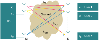
Figure 1 MU-MIMO model.
As we move towards a fifth generation (5G) of wireless networks, the growth in smartphone subscriptions and new wireless applications has resulted in predicted capacity requirements of 100x beyond Long Term Evolution (LTE)–4G.1 These predictions are now being whittled down into requirements by the 3rd Generation Partnership Project (3GPP) and standardization is well underway.2 A new physical layer technology that has received a lot of attention in recent years is Massive multiple-input, multiple-output (MIMO), with its ability to dramatically ramp up spectral efficiency figures to unprecedented levels.
In a time where usable spectrum is scarce and expensive, this is a highly attractive solution for operators to increase the capacity possible within the sub-6 GHz bands, and an early form of the technology known as Full-Dimension (FD) MIMO was already considered as early as LTE Release 13.3 Whilst much progress has been made, Massive MIMO is far from a mature solution. It is still an active research and development area for academia and industry alike, as engineers try to achieve the theoretical gains with commercially deployable solutions.
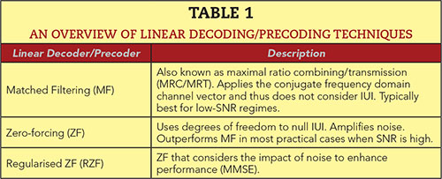
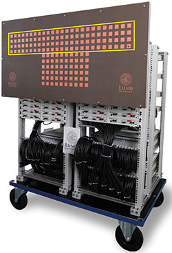
Figure 2 Lund 100-antenna Massive MIMO testbed.13
From an operator perspective, Massive MIMO is able to assist in solving two of the key challenges in the Radio Access Network (RAN) —capacity and coverage. Spectrum remains a scarce and relatively expensive resource for mobile operators, but is a key driver of RAN capacity and headline speed. This is particularly the case in many cities where base station spacing is driven by capacity rather than coverage, which requires a dense cell deployment incurring additional costs for the base stations and site acquisition. The high spectral efficiency delivered by Massive MIMO spatial multiplexing offers an opportunity to deliver capacity increases using existing sites. In areas where cell deployment is driven by coverage rather than capacity, there are also opportunities to use Massive MIMO array gain to increase the range of the base station—particularly when using spectrum between 2 and 6 GHz.
MASSIVE MIMO CONCEPT
Massive MIMO is an evolution of the Multi-User (MU) MIMO multi-antenna technique that exploits multipath scattering to increase system capacity.4 The generic MU-MIMO model is shown in Figure 1, where an M antenna base station (BS) serves up to K single-antenna user terminals on the same time-frequency resource. M is greater than or equal to K and, strictly speaking, the terminals can each have multiple antennas, but as this is not a requirement, it has been omitted for simplicity. All BS antennas have full RF chains with digitization behind them and the signal processing associated with Massive MIMO is uniquely applied to each signal path from the RF head.
With sufficient spacing between the BS antennas and well dispersed user terminals, independent multipath channels between each BS antenna and user terminal are formed, providing additional degrees of freedom in space. By appropriately precoding the symbols for each user terminal onto the BS antennas using channel knowledge, these spatial degrees of freedom can be harnessed to simultaneously serve multiple user terminals within the same frequency band—a process known as spatial multiplexing. MU-MIMO is already present within both LTE Advanced and the 802.11ac Wi-Fi standard.
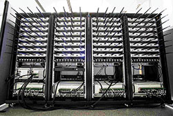
Figure 3 Bristol 128-antenna Massive MIMO testbed, which is managed by Bristol Is Open (BIO), a joint venture between the University of Bristol and the Bristol City Council.
In a Massive MIMO system, the number of BS antennas is increased significantly to far outweigh the number of user terminals served, typically by a factor of 10. This increase in degrees of freedom serves to better guarantee spatial orthogonality between users, reducing inter-user interference (IUI) and providing for a more stable, deterministic spatial multiplexing gain when using MU-MIMO. A large amount of array gain is possible, which permits low-power RF chains for the same range, and the law of large numbers also comes into play to average out the effects of noise, fast-fading and hardware impairments.
Furthermore, the natural orthogonality gained in the spatial dimension permits low-complexity linear decoding and precoding at the BS, reducing computational overheads and latency. An overview of the common linear techniques is given in Table 1. The user terminal itself does not need to do anything other than transmit its training signal—the BS does the rest. Massive MIMO does not encompass all systems with a large array of antennas, some of which often perform more conventional beam steering, but specifically those systems that use many tens or hundreds of digital RF chains to conduct robust spatial multiplexing.
It should also be noted that whilst using millimeter wave frequencies may seem attractive from an array size perspective, there are several issues with this: high path-loss, prohibitively expensive Full Massive MIMO processing (see Table 1) across GHz bandwidths and rapid multipath channel decoherence. For these reasons, millimeter wave systems with large arrays tend to apply a hybrid approach, with analogue beam steering to compensate for link budget, followed by a reduced level of digital MIMO operation within the analogue beams.
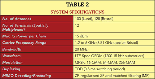
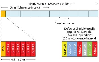
Figure 4 TD LTE-like PHY frame schedule.
As the number of antennas on the BS side increases, so too does the number of channels that require training. To avoid infeasible training overheads and reach maximum capacity, Massive MIMO must operate in time-division duplex (TDD) mode and exploit channel reciprocity. In doing so the number of orthogonal training signals required is no longer dependent upon M but solely the number of user terminals present. However, frequency-division duplex (FDD) Massive MIMO solutions are being explored as a large percentage of the world’s 4G networks currently operate in this mode.
IMPLEMENTING MASSIVE MIMO
The momentum for making Massive MIMO happen has built tremendously in the past year. ZTE has released a Pre5G Massive MIMO BS,5 demonstrating a 4 to 6x improvement in spectral efficiency through various trials, and Nokia, jointly with Sprint, demonstrated a Massive MIMO solution at Mobile World Congress 2017.6 Facebook has constructed a Massive MIMO prototype for long-range rural access7 and even Intel has joined the party to provide its own processing solution for large-scale MIMO systems.8
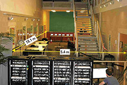
Figure 5 Indoor trial one: University of Bristol lower atrium.14
Going back a few years prior to these developments, Lund University in Sweden partnered with the Advanced Wireless Research Group at National Instruments in 2014 to construct the world’s first Massive MIMO testbed.9 The University of Bristol joined the collaboration in 2015 to contribute to the ongoing software development having constructed a Massive MIMO platform of its own using the same hardware. These two systems are shown in Figure 2 and Figure 3, respectively. These systems were constructed entirely from commercial-off-the-shelf (COTS) hardware components all linked together using Gen-2 PCIe. An overview of the specifications can be found in Table 2.
In implementing the systems, there were two key challenges: data handling and processing latency. For a single 20 MHz LTE band, each RF chain is producing and consuming 30.72 MS/s, which equates to 122.9 MB/s/chain when using 4 bytes/sample. For a 128-antenna system, this sums up to a bidirectional rate of 15.7 GB/s. Not only is this a lot of data to process, but a fast TDD switching period of 0.5 ms is required to ensure channel validity for the downlink and this brings with it a strict requirement for processing latency. The schedule shown in Figure 4 illustrates the orthogonal frequency-division multiplexing (OFDM) symbol layout across one full 10 ms radio frame and specifically the seven OFDM symbols within one 0.5 ms slot. Following reception of the UL Pilot symbol, the precoding matrices for all frequency domain resource blocks must be available and samples ready for transmission just three OFDM symbols (214 µs) later.
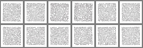
Figure 6 UL Constellations from each user terminal in indoor scenario 1 after ZF decoding.14
The per chain data rate was reduced by performing OFDM modulation and demodulation at the RF front-end utilizing Kintex 7 FPGAs present on the software-defined radios (SDR). At subcarrier rate with 3 bytes per complex sample, each chain has a bidirectional throughput of 50.4 MB/s. Sixteen antenna subsystems were then formed with careful sample routing to provide eight bidirectional links of 806.4 MB/s back to the central MIMO co-processors—a sum bidirectional rate of just under 6.5 GB/s. At the heart of the system, a further four Kintex 7 FPGAs perform 128 × 12 (M × K) MIMO processing on a quarter of the bandwidth each (300 subcarriers).
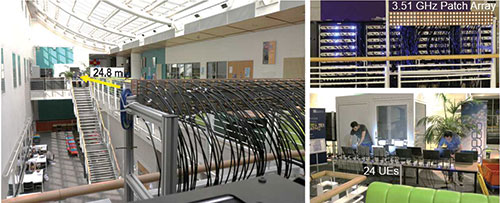
Figure 7 Indoor trial two: University of Bristol upper atrium.15
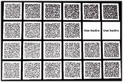
Figure 8 Uplink constellations for 22 users following ZF decoding in indoor trial 2.15
The maximum peer-to-peer link rate of each co-processor across PCIe is 2.4 GB/s, which means three co-processors would have satisfied the throughput requirement; however, four were chosen to further lower the burden on low-latency design. Each co-processor must perform channel estimation and form linear decoding and precoding matrices for its portion of bandwidth. The linear decoding and precoding options included in the design were matched filtering (MF), zero-forcing (ZF) and regularized ZF, the latter two of which require matrix inversions.
Using a QR decomposition for matrix inversion implemented through a modified Gram-Schmidt process with a partially parallel systolic array,10 these four FPGA card co-processors clocked at 200 MHz met the throughput requirement of 1.4 million matrices/s. Clearly, implementing a fully digital Massive MIMO solution is far from trivial, but these systems went on to demonstrate just how huge the spectral efficiency gain can be.11,12
EXTREME SPECTRAL EFFICIENCY
Through enhanced MU-MIMO spatial multiplexing, Massive MIMO provides the opportunity to ramp-up spectral efficiencies to unprecedented levels by serving multiple user terminals on the same time-frequency resource. The theoretical results were promising, but until recently there had been little in the way of publicized demonstration of real implementations achieving such gains.
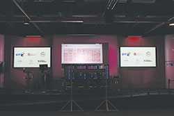
Figure 9 Bristol Massive MIMO testbed receiving 64–QAM from 24 user clients at Adastral Park (BT R&D).
In early 2016, with newly implemented real-time systems, the University of Bristol and Lund University ventured out of the lab for the first time to see what was possible. Within an indoor atrium environment at the University of Bristol, a 5.4 m long linear array of 112 dipole antennas was used to serve 12 user terminals at a distance of 18 m (see Figure 5). The user terminals were closely spaced (2.5 to 6 λ) and configured for uplink only transmission using 256-QAM. In this scenario, a record breaking spectral efficiency of nearly 80 bits/s/Hz was achieved with a rate of 132 Mb/s from each user terminal; a sum rate of 1.59 Gb/s in 20 MHz of bandwidth. The clarity of the received constellations in Figure 6 illustrates just how well the system mitigated IUI with linear decoding alone (ZF).
Two months after this first trial, armed with a new 128-element patch array, a second indoor trial was conducted in the upper atrium of the same building. This time, modifications were made to enable up to 24 user terminals to be served, and the aim was to see how far it could really be pushed. At a distance of nearly 25 m, the BS and user terminals were placed at opposite ends of the atrium as shown in Figure 7. The BS array had a 4 × 32 configuration with alternating H&V polarizations, thus still exhibiting dominance in the azimuth, and the user terminals were bunched in a straight line with the same 2.5 to 6λ spacing as the first trial.
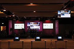
Figure 10 Bristol Massive MIMO testbed demonstrating spatially multiplexed HD video transmission from 10 users.
Once again transmitting with 256-QAM in the uplink, it was possible to spatially multiplex up to 22 user terminals and infer an achievable spectral efficiency of nearly 146 bits/s/Hz through post-emulation (nearly 3 Gb/s in only 20 MHz of bandwidth). The received constellations are shown in Figure 8 and once again illustrate the excellent IUI mitigation achieved with ZF. In this scenario, adding a 23rd user caused a significant reduction in the SINR.14,15
To gain perspective and insight from a network operator, the two universities and National Instruments subsequently conducted trials in early 2017 jointly with British Telecom (BT) at BT Labs in Adastral Park, Suffolk, U.K.16 Within an exhibition hall environment using the 128-antenna system, 24 user terminals were served with over-the-air (OTA) synchronization and up to 64-QAM modulation, inferring a spectral efficiency of over 100 bits/s/Hz (see Figure 9). Also, spatially multiplexed HD video transmission from 10 user terminals was demonstrated (see Figure 10). When compared to the second indoor trial conducted at the University of Bristol, this shows how the spatial multiplexing performance can vary within different environments. Whilst these results served to indicate the staggering gains possible with Massive MIMO, the next step was to consider outdoor environments and user terminal mobility.
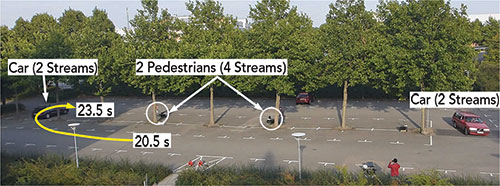
Figure 11 Fading scenario as viewed from the BS.13
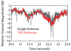
Figure 12 Comparison of channel magnitude over time: 100 antennas vs. single antenna.13
MOBILITY
It has been expected that mobility will pose problems for Massive MIMO due to the impact of channel ageing upon decoding and precoding. With a linear technique such as zero-forcing, deeper nulls are placed upon interfering users with far greater precision in Massive MIMO, but this leaves less margin for error. The system is more sensitive to steep rises in IUI from terminal movement. Increasing the channel resounding interval may help to overcome this, but it ultimately eats into the coherence interval and limits the number of user terminals that can be served.
In the summer of 2016, Lund University and the University of Bristol conducted the world’s first publicized demonstration of a real-time Massive MIMO system operating with mobile channel conditions. The 100-antenna Lund BS operating at 3.7 GHz was placed upon a third story rooftop and served multiple cars travelling at up to 50 km/h within a car park 30 to 50 m away. The scenario was predominantly line-of-sight (LOS) and a 4 × 25 azimuth dominated BS array configuration was used with alternating H&V polarizations. Configured as a mixture of bicycle carts and cars, up to eight user terminals were spatially multiplexed with both uplink and downlink transmission, and each terminal transmitting at a fixed power of 0 dBm.
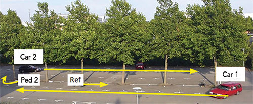
Figure 13 Temporal correlation scenario for Car 2.13
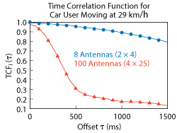
Figure 14 Comparison of channel decorrelation: 100 antennas vs. 8 antennas.13
The 80th percentile real-time bit error rate (BER) achieved for all eight users in this scenario was 1 percent on the uplink and 10 percent on the downlink when using QPSK with no power control, user grouping or coding. A video of the demonstration can be found at: www.youtube.com/watch?v=wPPMrr4rHmo.
Some of the key insights from this measurement trial came from analyzing the temporal aspects of the measured channel data. By ensuring the uplink pilot symbols were captured at or above the Nyquist spatial rate (λ/2 sample spacing) for the periods of interest, an accurate picture of the channel behavior over time could be formed. Figure 11 illustrates one portion of a scenario where the composite channel magnitude between the BS and one car user terminal was observed. This is the view from the BS array and the path of the car of interest over the three seconds is illustrated by a yellow arrow.
In Figure 12, the normalized composite channel magnitude for the full 100 antennas is compared with that of a single BS antenna over the same three second period. The Massive MIMO case smooths out the Rician-like fading experienced by one antenna due to the huge gain in spatial diversity. In fact, inspecting the power correlation over time for this same period indicated that power control update rates could be reduced by 5x for the 100-antenna case.
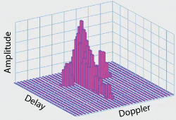
Figure 15 OTFS Delay-Doppler domain.18
As previously mentioned, the critical aspect for Massive MIMO when it comes to mobility is the increased rate of channel decorrelation. To gain some insight into what the impact could be, a second scenario was established as pictured in Figure 13. The user object of interest is Car 2, which moves across the car park in the direction of the arrow at a speed of 29 km/h—at this speed, the Nyquist rate is satisfied for the 5 ms channel capture rate used. Time-shifted correlations of the channel vector for this user were then performed, the results for which are shown in Figure 14. By comparing the 100-antenna results to those from an 8-antenna configuration, the significant increase in decorrelation rate can be clearly seen.
Here, the 100-antenna system experiences a rate of decorrelation 7x greater than the 8-antenna system. The 90 pecent coherence time of 125 ms is still relatively large, but an outdoor LOS scenario with minimal scattering represents a best case for channel coherence. In addition to these results, which were recently published,13 other measurements have begun to indicate just how severe the situation can be for non-line-of-sight (NLOS) scenarios, with a reported 90 percent coherence time of 500 ms with only 0.1 km/h of mobility.17
LOOKING TO THE FUTURE
Massive MIMO has set the stage for an unprecedented level of spectral efficiency, and will without a doubt feature in 5G wireless communication systems. Despite the advance of millimeter wave, the propagation characteristics of sub-6 GHz technology are more desirable for many scenarios, and Massive MIMO is therefore crucial for squeezing more out of the lower bands.
At first glance, it appears high-mobility could cause some difficulties for Massive MIMO deployments, but this may or may not be a problem depending upon the applications and environments it targets. In outdoor—LOS scenarios over greater range—the channel decoherence rates with typical vehicular speeds could potentially be tolerated with little training overhead. On the other hand, NLOS, dense-urban environments with rich multipath scattering will provide more rapid channel decoherence, but this may be tolerable with pedestrian level speeds.
One exciting possibility is to entirely change the way we view the channel and modulate signals, and an emerging wireless modulation technology called Orthogonal Time Frequency and Space (OTFS) is doing just that.18 Rather than take snapshots of the frequency domain channel, OTFS formulates a 2D representation of the wireless channel in the Delay-Doppler domain (see Figure 15). By choosing suitable time and bandwidth observation intervals, this essentially provides a complete representation of the wireless channel by indicating the delay and Doppler shift of each multipath component, just like a radar. Since the environment and Doppler trajectories change relatively slowly compared to the time-varying multipath channel, the Delay-Doppler coherence time is greater than that of the frequency domain.
This means OTFS could enable closed-loop Massive MIMO operation in conditions that OFDM cannot. By performing modulation in the Delay-Doppler domain using 2D basis vectors, the energy of each symbol is spread across time and frequency, utilizing the full diversity of the wireless channel. The result is a static channel response and stable SNR. Early results have shown that OTFS not only outperforms OFDM, but can operate using 64-QAM at 500 km/h, whilst OFDM must drop down to 16-QAM at this speed for a suitable Block Error Rate (BLER).
However, despite all the above, there are many challenges that need to be solved before Massive MIMO becomes mainstream for operators. These include:
- Potentially higher costs associated with maintaining Massive MIMO implementations that are based on Active Antenna Units (AAU), where the radio electronics are integrated with the antennas and installed at the top of the radio towers. These can only be maintained by skilled rigging teams. While this issue could be partially mitigated by the fact that a single element failure may not greatly impact overall performance, further study is required.
- The impact of Massive MIMO systems on radiated power limits. The potential antenna gain from these systems may have a significant impact on the International Commission on Non-Ionizing Radiation Protection (ICNIRP) compliance.
- The availability of tools to perform Massive MIMO radio planning.
References
- Ericsson, “Ericsson Mobility Report,” www.ericsson.com/en/mobility-report.
- T. Norp, “5G Service Requirements,” 27 February 2017, www.3gpp.org/news-events/3gpp-news/1831-sa1_5g.
- D. Flore, “Evolution of LTE in Release 13,” 18 February 2015, www.3gpp.org/news-events/3gpp-news/1628-rel13.
- T. L. Marzetta, “Noncooperative Cellular Wireless with Unlimited Numbers of Base Station Antennas,” 7 October 2010, www.ieeexplore.ieee.org/document/5595728/.
- ZTE, “Pre5G Massive MIMO Base Station,” 2017, www.zte.com.cn/global/products/wireless/Base-Station-Series/Pre5G-Massive-MIMO-Base-Station.
- Nokia, “Nokia and Sprint Demonstrate Massive MIMO at MWC17,” 27 February 2017, www.nokia.com/en_int/news/releases/2017/02/27/nokia-and-sprint-demonstrate-massive-mimo-at-mwc17.
- C. Metz, “Facebook’s Massive New Antennas Can Beam Internet for Miles,” Wired, 13 April 2016, www.wired.com/2016/04/facebooks-massive-new-antennas-can-beam-internet-miles/.
- Intel, “Intel Accelerates the Future with World’s First Global 5G Modem,” 4 January 2017, www.newsroom.intel.com/editorials/intel-accelerates-the-future-with-first-global-5g-modem/.
- National Instruments, “National Instruments and Lund University Announce Massive MIMO Collaboration,” 24 February 2014, www.ni.com/newsroom/release/national-instruments-and-lund-university-announce-massive-mimo-collaboration/en/.
- Y. Rao, “Implementing Modified QR Decomposition in Hardware,” U.S. Patent US20140214910 A1, 31 July 2014.
- S. Malkowsky, J. Vieira, K. Nieman, N. Kundargi, I. Wong, V. Owall, O. Edfors, F. Tufvesson and L. Liu, “Implementation of Low-Latency Signal Processing and Data Shuffling for TDD Massive MIMO Systems,” 12 December 2016, www.ieeexplore.ieee.org/document/7780107/.
- S. Malkowsky, J. Vieira, L. Liu, P. Harris, K. Nieman, N. Kundargi, I. C. Wong, F. Tufvesson, V. Owall and O. Edfors, “The World’s First Real-Time Testbed for Massive MIMO: Design, Implementation and Validation,” 18 May 2017, www.ieeexplore.ieee.org/document/7931558/.
- P. Harris, S. Malkowsky, J. Vieira, F. Tufvesson, W. B. Hasan, L. Liu, M. Beach, S. Armour and O. Edfors, “Performance Characterization of a Real-Time Massive MIMO System with LOS Mobile Channels,” IEEE Journal on Selected Areas in Communications (JSAC), Vol. 35, No. 6, 2017, pp. 1244–1253.
- P. Harris, S. Zhang, M. Beach, E. Mellios, A. Nix, S. Armour, A. Doufexi, K. Nieman and N. Kundargi, “LOS Throughput Measurements in Real-Time with a 128-Antenna Massive MIMO Testbed,” presented at IEEE Globecom 2016, Washington D.C., 2016.
- P. Harris, W. B. Hasan, S. Malkowsky, J. Vieira, S. Zhang, M. Beach, L. Liu, E. Mellios, A. Nix, S. Armour, A. Doufexi, K. Nieman and N. Kundargi, “Serving 22 Users in Real-Time with a 128-Antenna,”presented at IEEE International Workshop on Signal Processing Systems, Dallas, 2016.
- University of Bristol, “Bristol and BT Collaborate on Massive MIMO Trials for 5G Wireless,” 24 February 2017, www.bris.ac.uk/news/2017/february/massive-mimo-trials.html.
- C. Shepard, J. Ding, R. E. Guerra and L. Zhong, “Understanding Real Many-Antenna MU-MIMO Channels,” presented at Conference on Signals, Systems and Computers, 2016 50th Asilomar, Pacific Grove, Calif., 2016.
- Cohere Technologies, “Constant 1 Gbps at 500 Km/h,” 2017, www.cohere-technologies.com/.
- R. Hadani, S. Rakib, M. Tsatsanis, A. Monk, A. J. Goldsmith, A. F. Molisch and R. Calderbank, “Orthogonal Time Frequency Space Modulation,” presented at Wireless Communications and Networking Conference (WCNC), 2017 IEEE, San Francisco, 2017.