Even as fourth-generation (4G) cellular systems—LTE and LTE-Advanced—are being deployed, research and active development has begun on fifth-generation (5G) systems. 5G mobile networks offer a vision of everything, everywhere and always connected. In a 5G system, key attributes may include a dense, highly flexible network comprised of small cells supporting data rates on the order of 10 Gbps, with roundtrip latency of 1 ms or less. Most studies assume multiple air interfaces operating at microwave or millimeter frequencies—the new radio (NR). 5G NR has three basic use cases: enhanced mobile broadband (eMBB), massive machine-type communications (MMTC), ultra-reliable and low latency communications (URLLC). Achieving this vision will require a combination of evolution and revolution in technology, business models and policy.
As a policy example, the U.S. Federal Communications Commission (FCC) recently announced new rules to enable rapid development and deployment of next-generation 5G technologies and services.1These rules create a new flexible use service in the 28, 37 and 39 GHz frequency bands, as well as a new unlicensed band from 64 to 71 GHz. This new band, combined with the existing unlicensed band from 57 to 64 GHz, opens up a 14 GHz span of unlicensed spectrum from 57 to 71 GHz, some of which lies well outside the high absorption peak associated with oxygen.
The movement to the new frequency bands at 28 GHz and above will bring new challenges in the development of power amplifiers (PA), both for base stations and mobile devices. At 28 GHz, 100 MHz wide carriers are expected, with carrier aggregation providing signals as wide at 800 MHz. At 60 GHz and above, carriers are already 2 GHz wide with 802.11ad. Proposals for 802.11ay add aggregation or bonding of two or more of these channels. It is expected that 5G will use similar bandwidths in these frequency bands. Using these frequency bands and signal bandwidths requires a new wave of signal generation and analysis equipment.

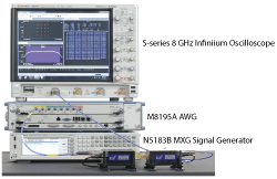
Figure 1 Test equipment used for 60 GHz DPD measurements.
With 3G and 4G cellular communication, digital predistortion (DPD) was used to allow PAs to operate with higher efficiency without sacrificing modulation quality. This became important as the peak-to-average ratios (PAPR) of the signals increased, so did the demand to reduce the power consumption of the amplifiers. With 5G, the proposed waveforms may demand even higher PAPR. DPD compensates for the AM/AM and AM/PM distortion in the amplifier. In the simplest form, the inverse of the AM/AM and AM/PM curves can be applied to the input signal, producing the ideal signal at the output. In practice, it is also important to consider memory effects in the amplifier, which are exacerbated with very wide signal bandwidths. Circuit models that are typically used for the design and simulation of PAs cannot predict the memory effect, and the only practical way to deal with it is to test the PA and capture the time domain modulated signal after it passes through the amplifier. Established techniques typically require that the input signal be generated and measured at 3 to 5× the bandwidth of the signal.
The test equipment available for testing 4G PAs could easily handle these sample rates, even for the widest 20 MHz LTE signals. For 5G and 802.11ad signals with bandwidths as wide as 2 GHz, the techniques used for 4G are beyond the capabilities of most vector signal generators (VSG) and vector signal analyzers (VSA) currently available.

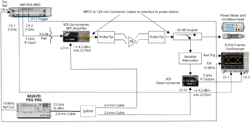
Figure 2 Block diagram of the 60 GHz test system. The M8195 AWG, E8267D VSG and oscilloscope were connected via LAN.
A DIFFERENT APPROACH
To address the DPD bandwidths of 5G and 802.11ad, wide bandwidth arbitrary waveform generators (AWG) and oscilloscopes can be used to generate and analyze intermediate frequency (IF) signals, with up- and down-converters to convert the IF signals to the required carrier frequencies.

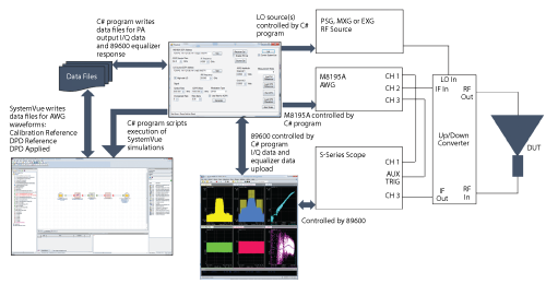
Figure 3 Test system software structure.

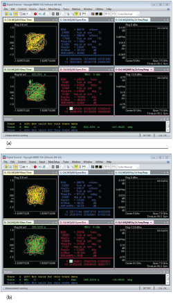
Figure 4 ACPR performance without DPD (a) and with DPD (b).
To perform DPD measurements on a Skyworks 60 GHz PA designed for 802.11ad, the Keysight M8195A 8-bit, 65 GSPS AWG and S-Series 10-bit, 20 GSPS oscilloscope were used with compact up- and down-converters from Virginia Diodes Corporation (VDI). Using second harmonic mixers, the up- and down-converters require a local oscillator (LO) signal that is one half the final LO frequency. A Keysight 40 GHz continuous wave (CW) signal generator was used to generate the LO. Figure 1 shows the equipment used and Figure 2 shows the block diagram of the test setup. One channel of the AWG was used to generate an IF signal at approximately 4 GHz. Since the same LO signal was used for both up- and down-conversion, the IF input to the scope was also centered at 4 GHz. Using this approach, almost the entire 8 GHz bandwidth of the scope could be used to capture the signal. For the DPD analysis, QPSK and 64-QAM signals were generated with a 1.5 GHz symbol rate and an occupied bandwidth of approximately 2 GHz. The signal was generated and analyzed at a 7.5 GHz sample rate, 5× the symbol rate. For the AWG, the 7.5 GSPS I/Q signal was modulated to the IF frequency in software and up-sampled to the AWG sample rate in the range of 56 to 65 GHz. The DPD measurements were performed on wafer. One advantage of the VDI up- and down-converters is their small size, allowing them to be placed very close to the probes to minimize the cable loss.
Keysight SystemVue and 89600 VSA software were central to the measurements and analysis. SystemVue generated the test waveforms and performed DPD model extraction, then applied the DPD model to generate predistorted waveforms. The VSA software measured the error vector magnitude (EVM) and adjacent channel power (ACP) visualized the AM/AM and AM/PM conversion and extracted the I/Q data for the DPD model. A C# program coordinated the software applications and controlled the M8195A and LO signal generators. Figure 3 shows a block diagram of the software structure.
MEASUREMENT RESULTS
Two different devices under test (DUT) were measured. One was a single-stage PA fabricated on a 45 nm SOI CMOS technology with approximately 7.5 dB gain and a CW 1 dB compression point (P1dB) of approximately 11 dBm and saturated output power (Psat) of around 15 dBm. The other DUT, fabricated on the same semiconductor platform, was a three-stage PA with 14 dB gain and a CW P1dB of approximately 15 dBm. In designing the PA, the goal was to render an amplifier with minimum AM/AM and AM/PM distortion and little or no memory effect. Variation of AM/PM across the design frequency band is a measure of the amplifier’s memory effect; sudden variations in AM/PM versus frequency are symptoms of linearization problems.2

Figure 5 EVM performance without DPD (a) and with DPD (b).
The DPD measurements were performed at several RF input power levels for the single-stage PA and over a range of input power for the three-stage PA. In general, DPD provided 2 to 4 dB of improvement in ACP and a 1 to 2 point improvement in EVM, compared to results without DPD. Figures 4 and 5 show the ACP and EVM results for a single test case of the three-stage PA. Figure 4a shows the lower and upper ACP levels without DPD are -28.8 dB and -27.7 dB, respectively. With DPD (see Figure 4b), the lower and upper adjacent power levels are -32.9 dB and -30.2 dB respectively. DPD improves the lower and upper levels by 4.1 dB and 2.5 dB, respectively. EVM performance improves 1.4 points, from 4.9 percent without DPD (see Figure 5a) to 3.5 percent with DPD (see Figure 5b).
Several approaches were used to properly model the PA; a third-order memory polynomial with one memory span most accurately represented PA behavior. This eliminated the need to use more complicated Volterra models, even at high compression values.
CONCLUSION
This new, flexible millimeter wave test system is capable of very wideband signal generation and analysis to research amplifier DPD at 60 GHz. Key components of the test bed include the M8195A AWG, VDI WR15 compact up- and down-converters, wideband DSO S-Series oscilloscope, 89601B VSA software and SystemVue. Digitally-modulated single-carrier waveforms were generated and measurements performed in the 60 GHz band with a sample rate of 7.5 GHz. These wide bandwidth measurements enabled DPD model extraction with SystemVue, and the model successfully demonstrated improved amplifier linear performance, both ACPR and EVM. Using other available converters, the system can be expanded to research other millimeter bands such as 64 to 71, 71 to 76 and 81 to 86 GHz.
References
- Press release: FCC Takes Steps to Facilitate Mobile Broadband and Next-Generation Wireless Technologies in Spectrum Above 24 GHz, https://apps.fcc.gov/edocs_public/attachmatch/DOC-340301A1.pdf
- O. Hammi, S. Carichner, B. Vassilakis and F. M. Ghannouchi, “Power Amplifiers’ Model Assessment and Memory Effects Intensity Quantification Using Memoryless Post-Compensation Technique,” IEEE Transactions on Microwave Theory and Techniques, Vol. 56, No. 12, pp. 3170–3179, December 2008.
