
Figure 1 ITU vision for IMT-2020, including usage scenarios (a) and enhancement of capabilities from IMT-Advanced (b).
Not a day goes by that we don’t encounter the terms 5G and IoT (Internet of Things). Indeed, the future is about super-connectivity and the promise it gives us, once everything is “talking” with each other. Connected appliances to connected cars, making life easier as we prepare for smart homes, smart cities and smart everything. It is difficult to imagine this future—yet so was imagining 2015 when looking through the view of the internet in the year 2000.
There appear to be as many definitions of 5G and IoT as forecasts and opinions when discussing the potential benefits and relevant business cases of these technologies. The International Telecommunication Union (ITU) has been working on defining what 5G IMT-2020 will be from a technical perspective, or at least how it will differ in performance from 4G (IMT-Advanced). The term 5G IMT-2020 was coined in 2012 by the ITU Radiocommunication sector and means “international mobile telecommunication system,” with a target date of 2020. Within that definition, we see how IoT will benefit. Parameters like peak data rates, mobility, latency and spectrum efficiency are important, as they help define what the user experience will be, key to enhanced mobile broadband (eMBB) and ultra-reliable and low latency communications (URLCC). Figure 1 shows how the ITU envisions 5G.
IoT, on the other hand, will need different parameters to operate in a way that needs minimal to no user action on a day-to-day basis, after the initial setup. Today, we are seeing the beginning of the IoT market, an expansion of the M2M market that already exists and accounts for 600 million devices as of 2015.1 The IoT can be divided into two segments.2 The first represents massive IoT connections with high connection volume, low cost, low energy consumption and small data traffic. The second comprises critical IoT connections that require ultra-reliability and availability with very low latency. Table 1 shows applications for each of the two classifications. Figure 2 shows a forecast for the connected devices market, based on Ericsson’s mobility report.3 The traditional connected-device market of fixed, mobile phones and computer/tablets will increase slightly, while the overall number of devices associated with IoT, both cellular and non-cellular, will grow greater than 20 percent annually. The IoT space can also be viewed by how connectivity is achieved, particularly using low power technology. Various low power standards are summarized in Table 2.
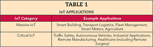
Figure 2 Connected devices forecast, from 2016 Ericsson Mobility Report.
Frequency band allocations for 5G focus heavily on available bandwidth, and they seem to center around three groups: sub 6 GHz, 15 to 40 GHz and greater than 60 GHz. Because much of 5G will be data intensive, the frequencies around 28, 39 and 77 GHz are gaining momentum because of the availability of spectrum within those bands. As many IoT applications are expected to be low data rate, most of the IoT activity is centering on the sub-6 GHz spectrum. An exception will be IoT for surveillance, where transmitting high definition video from remote areas may require the bandwidth found in the millimeter wave spectrum.
MATERIALS PERSPECTIVE
Printed circuit boards (PCB) are a building block in any electronic system. The choice of PCB material for RF applications depends on frequency, power level, circuit size and function. Designers have choices from basic epoxy/glass materials (FR-4), mid-loss materials and, ultimately, high end microwave/millimeter wave materials. The most common PCB material is FR-4, mainly developed for the mechanical properties key to multilayer circuit boards. Variations of these materials exist, offering dissipation factor (Df) or loss tangent values ranging from 0.01 to beyond 0.02 (see the tier 1 and 2 materials in Figure 3). The focus of these materials has been low cost and ease of manufacturing for complex multilayer boards, with no real attention on repeatability of electrical properties, since the applications where these are used don’t require that level of performance. The second set of materials use specialty resins, sometimes blended with epoxy, and achieve some improvement in loss. These materials have mainly been used in high speed digital applications up to 10 Gbps. The last group is defined as high frequency material (found in tiers 5 and 6), where the Df is less than 0.005.
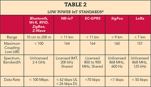
Figure 3 PCB material classification by loss tangent (Df).
Various parameters are considered in the selection process when deciding which type of PCB material to use: loss, dielectric constant, thickness, thermal conductivity and, let’s not forget, cost. In the end, it is about selecting the appropriate material at the right cost. Much of the IoT market today is using traditional FR-4 in the transceiver or antenna portions of the radio. However, there is a subset of this market that requires a higher level of reliability, including industrial, medical, traffic control, automotive and smart meters. This subset is taking advantage of the higher performance materials and the increased focus on reliability that tier 5 and 6 materials can provide.
So what are the benefits of selecting a high performance material instead of FR-4? The first benefit a designer will notice is the impact loss tangent has on the loss of the circuit. Many times, this is the primary consideration. This difference can be almost an order of magnitude greater with some materials. To keep it simple — and not include in the analysis the impact dielectric constant has as Dk of FR-4 is 4.4 and many high frequency materials options are lower — consider the simulated insertion loss for a 50 Ω transmission line on FR-4, with Dk = 4.4 and a dielectric thickness of 0.020". The 50 Ω width is calculated to be 0.038".5 Comparing the change in insertion loss when Df varies from 0.02 to 0.004 at 2.4 GHz for this line width, the insertion loss is 0.24 dB/inch for a Df of 0.02; for a Df of 0.004 the insertion loss will only be 0.01 dB/inch. The benefit here is that if the circuit is an antenna, the lower loss improves the sensitivity and will extend the range of the antenna.
Figure 4 Normalized dielectric constant vs. temperature.
In some cases, it is not the loss of the material that is the main driver for selecting a high performance material; sometimes it is the variability of the dielectric constant. Most high performance materials have a tolerance of less than ±2 percent, even less for materials with low dielectric constant, while FR-4 materials can be greater than ±5 percent. The increased variability of the FR-4 may require the circuits to be tuned to ensure they operate within the frequency specified, while materials with tighter tolerance will not need such optimization.
Environmental changes can affect the dielectric constant of FR-4, yet have minimal impact on high performance materials. FR-4 has significantly higher moisture absorption than high performance materials. This leads to an increase in Dk (also Df). If the circuit needs to operate in a high moisture environment—tropical areas such as Malaysia—FR-4 materials have been known to drift, due to the change in dielectric constant. In comparison, moisture has minimal impact on the dielectric constant of the high frequency laminates. Changes in the temperature can also have a significant impact on the operation of a circuit: with FR-4, notably, dielectric constant changes with temperature (see Figure 4). The change with FR-4 is close to an order-of-magnitude higher than with the more stable materials in the figure. FR-4 can change as much as 400 ppm/°C. With materials like RO3003™ and RO4350B™ laminate, the short-term change is close to 40 ppm/°C. Considering all these factors (i.e., tolerance, moisture absorption and temperature variation), selecting a high frequency material over FR-4 may be the best choice when a more consistent design is needed in the field.
In many cases, the IoT will be about having connectivity with a circuit as small as possible, due to limited space. In these cases, reducing the size of the antenna or circuit will be desired. By selecting materials with a dielectric constant of 6, 10 or higher, designs using FR-4 with a Dk of 4.4 can be reduced in size. Using a PCB with a Dk of 4.4, the wavelength at 1 GHz for 0.020" microstrip is about 7", while a material with a Dk of 10.2 (e.g., Rogers RO3010™ laminate), the wavelength is 4.4", close to a 40 percent reduction in size.5 Higher dielectric constant materials allow designers to shrink the size of the circuit board, saving area compared to FR-4.
There will also be IoT applications that operate at higher frequencies, potentially in the 28 to 40 GHz range, and not necessarily on low power networks where the use of high frequency materials is a must. Managing losses is extremely important, so using materials with low dissipation factors is critical, as well as selecting copper foils that are smooth, to reduce the conductor impact on insertion loss. In the case of materials based on PTFE resin, this is often addressed by using rolled copper foil instead of traditional electrodeposited copper foil. However, for materials that use low loss thermoset resins, using smooth foil impacts copper peel strength, in many cases lowering the value to the limit specified by the industry. To address this, Rogers introduced LoPro® copper foil to go with Rogers RO4000® materials, allowing designers to reduce insertion loss while maintaining copper foil peel strength to the level of standard copper.
Conclusion
5G and IoT have moved from if they happen to when they happen. It is likely that the applications that will revolutionize our lives may not yet have been thought of. What we do know is that many segments in the market will be undergoing significant change during the next few years. Smart homes, smart cities, remote health care monitoring, industrial controls and autonomous driving are topics of much interest. Many of these may benefit by using higher performance materials, especially for applications that use millimeter wave frequency bands. Much is yet to be defined about 5G and IoT, and we will no doubt see surprising use cases emerge. When asked, “Why did we connect a particular thing to the internet,” we may find ourselves saying “because we could.”
References
- Cisco, “Visual Network Index: Global Mobile Data Traffic Forecast Update, 2015-2020,” February 2016.
- International Communications Union, “IMT Vision–Framework and Overall Objectives of the Future Development of IMT for 2020 and Beyond,” September 2015.
- Ericsson, “Ericsson Mobility Report,” June 2016.
- Nokia, “From NB-IoT to 5G,” IWPC Workshop Presentation, October 2016.
- Simulation Using Rogers’ Microwave Impedance Calculator, www.globalcommhost.com/rogers/acs/techsupporthub/en/calculator.php.