
The latest generation of wireless picocells and chipsets impose challenging demands on duplexers. These cellular systems must increasingly support multiple band colocation, carrier aggregation, higher-order modulation, linearized power amplifiers or a combination of these requirements. The components used in these newer systems must achieve higher receive band rejection, extensive out-of-band rejection, higher peak power handling and improved reliability, with projected operating lifetimes increasing.
Better than SAW, BAW and FBAR
The filtering requirements for these systems can no longer be fully satisfied by surface-acoustic-wave (SAW), bulk-acoustic-wave (BAW), or film-bulk-acoustic-resonator (FBAR) filters, which typically have operating lifetimes of less than eight years and out-of-band rejection of less than 58 dB. These filters have peak-power-handling of +31.5 to +33 dBm (2 W) – at most +36 dBm (4 W). This is not sufficient for wireless systems operating at peak power levels of +37 to +38 dBm, due to the higher-order modulation used in LTE-Advanced cellular systems.
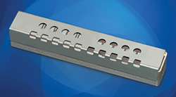
Figure 1 The USD004A duplexer has low insertion loss in the receive band from 1710 to 1755 MHz and the transmit band from 2110 and 2155 MHz, with high rejection outside each passband.
To address these challenges, CTS Corp. has developed three new families of ceramic surface-mount duplexers, offering three different tiers of performance and power handling: the UPD, USD and UMD duplexer families. Each family supports all the major frequency-division duplex (FDD) bands, from 698 MHz (band 12) to 2690 MHz (band 7). The filters have a universal footprint that enables a platform solution, using only a single printed circuit board (PCB) design and circuit layout.
The UPD family delivers more than 61 dB receive band rejection with less than 3 dB passband insertion loss (5 MHz average). This duplexer family handles average input power to 1.5 W and peak input power to 15 W. These duplexers are designed for multiple band picocells using linearized amplifiers, with 0.25 W typical at the picocell antenna.
The USD family of duplexers provides more than 71 dB receive band rejection with less than 2.6 dB insertion loss (5 MHz average). The USD family handles average input power to 6 W and peak input power to 60 W. These duplexers are well suited for power levels of 1 to 2.5 W at the antenna in outdoor small cells, indoor whole-band DAS or carrier-aggregation systems.
The UMD family of duplexers offers more than 80 dB receive band rejection with less than 2.2 dB insertion loss (5 MHz average). These duplexers handle 20 W average input power, 200 W peak. They are designed to support systems with 4 to 10 W power at the antenna, including outdoor metrocells, lower power indoor whole-band DAS or carrier-aggregation systems.
As examples, for a picocell using LTE Band 4, the model UPD004A duplexer covers the 1710 to 1755 MHz receive and 2110 to 2155 MHz transmit bands. Typical receive insertion loss is better than 1.2 dB over the full operating temperature range of -40° to +85°C; the transmit band insertion loss is also 1.2 dB or better. Rejection and isolation are greater than 63 dB over all operating conditions. The model UPD004A duplexer measures just 44.2 × 11.9 × 6.5 mm, including the shield. For the same LTE Band 4, the model USD004A is about 50 percent longer and taller than the model UPD004A, measuring 61.4 × 11.0 × 10.9 mm including the shield. This unit provides more than 72 dB isolation and rejection across the full set of operating conditions and supports the higher power levels necessary for applications with as much as 2.5 W at the antenna (see Figure 1). The unit weighs 14.1 g. For more demanding LTE Band 2 coverage, the UPD002A duplexer operates at the 1850 to 1910 MHz receive and 1930 to 1990 MHz transmit bands. It achieves receive-band attenuation of more than 60 dB with insertion loss held to 3 dB (see Figure 2). The duplexer measures 44.2 × 11.3 × 6.5 mm, including the shield.
Figure 2 The UPD002A duplexer has low insertion loss from 1850 to 1910 MHz and 1930 to 1990 MHz with high rejection outside each passband.
Figure 3 The UMBH05A bandpass filter has low insertion loss in the 869 to 894 MHz band, with high rejection from 824 to 849 MHz.
Competitive with Air Cavity
For applications requiring higher power-handling, such as outdoor metro cells delivering 5 W power at each antenna, these ceramic surface-mount filters can fill the roles once held by much larger and costlier air cavity duplexers. In Band 5, for example, the model UMD005A is a compact duplexer formed of a pair of bandpass filters, models UMBL05A and UMBH05A. The UMBL05A has a passband of 824 to 849 MHz with better than 2 dB passband insertion loss over -40° to +85°C. It measures only 56 × 15.8 × 14.5 mm, including shield. The other bandpass filter, model UMBH05A, has a passband from 869 to 894 MHz and better than 2 dB typical insertion loss across the same temperature range. It provides signal attenuation of 80 dB from 824 to 849 MHz (see Figure 3) and measures 56 × 15 × 14.5 mm (including shield). Both bandpass filters handle 20 W average and 200 W peak power.
The UPD, USD and UMD duplexer families are designed and constructed to deliver their rated performance across wide temperature ranges and long operating lifetimes, essentially for carrier-grade wireless infrastructure applications. In addition to saving space on PCBs, all of these filters are RoHS compliant. The technology can also be tailored to other market requirements and applications.
CTS Corp.
Elkhart, Ind.
www.ctscorp.com
RfFilters@ctscorp.com