
Today’s modern commercial and military communication systems are demanding better performance with regards to power, efficiency, linearity and operating bandwidth. As such, extra considerations must be placed on designing the internal components of the systems, including the low-noise and power amplifiers, to maximize performance.
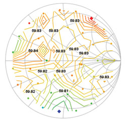
Figure 1 Drain efficiency load-pull contours at f0 on a harmonically-terminated transistor.
In order to reach higher efficiencies, significant research has been performed on designing high efficiency amplifiers by matching one or more harmonic impedances. An equally large effort has gone into designing commercial test systems which aid in the systematic identification of ideal matching impedances at the fundamental and harmonic frequencies, referred to as harmonic load-pull, in order to maximize performance.
Before venturing into a design project, it is important to ask several questions: Does the application require an amplifier with harmonic matching? If so, which test system is best suited to reach the design goals? This paper explores various types of amplifiers in order to identify which can or cannot take advantage of harmonic matching, and to compare and contrast various harmonic load-pull methodologies as they relate to amplifier design.
Harmonic Impedance Matching and its Relevance in Amplifier Design
Amplifiers are designed for various applications ranging from highly linear LNAs and PAs operating in Class A condition, to highly nonlinear PAs operating in advanced classes (E, F, G, J and their inverses). Some are designed using unmatched transistors while others are designed using partially (pre-matched or harmonically-terminated) - or fully-matched components. The design objective and the type of transistor used will dictate the need for harmonic impedance matching.
Amplifiers operating under linear (small-signal) conditions do not produce power at harmonic frequencies, and the output power of a device under test is linearly proportional to its input power. Because no power exists at harmonic frequencies, terminating the harmonic impedances should have no effect on the performance of a stable device under test (DUT). Several mathematical methods using S-parameters, including unilateral design and conjugate match, exist for determining the ideal input and output matches for maximum power and gain.1,2 Alternatively, fundamental-frequency load-pull can be used to identify ideal matching impedances for a given figure of merit.
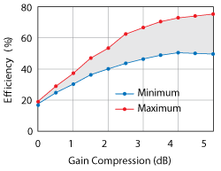
Figure 2 Drain efficiency as a function of compression, with harmonic termination.
Modern commercial and military systems may be required to operate over several octaves or over a decade in order to meet the frequency spectrum requirements of the application. As such, wideband amplifiers play a critical role in the overall performance of the radio or radar system, often dictating output power or gain flatness over the bandwidth. When designing an amplifier, the match at the fundamental frequency strongly influences the power and gain performance parameters. When dealing with wideband amplifiers, the ideal impedance match must be determined for subsets of the overall frequency range, and the matching network synthesized to achieve the desired wideband response. In this case, it is entirely possible that the harmonic frequencies (2fo, 3fo…) of the lower frequency band overlap a fundamental frequency in the middle or upper portion of the frequency band. When this happens, the ability to independently match the harmonic impedances at each fundamental frequency is drastically reduced or even eliminated.3,4 Consider a design example of a wideband amplifier operating between 3.1 and 10.6 GHz. For a fundamental frequency of 3.1 GHz, a theoretical Class-F amplifier would require a short at the second harmonic of 6.2 GHz and an open at the third harmonic of 9.3 GHz. However, 6.2 and 9.3 GHz are required fundamental frequencies of the wideband amplifier, and the short/open terminations could yield low performance at those frequencies.
Commercial packaged transistors are available from multiple vendors with varying degrees of integrated matching, varying from completely unmatched to partially matched and fully matched. Completely unmatched transistors can be tuned for maximum performance at a given frequency, power and bias by determining ideal loading conditions at the fundamental and harmonic frequencies, if harmonic power exists. Partially-matched and fully-matched transistors offer less flexibility as the internal matching structure within the packaged component limits the ability to significantly alter the match presented to the internal transistor. Partially- and fully-matched packaged transistors are commonly offered with optimum harmonic terminations already implemented for specific applications such as the design of commercial wireless base stations and handsets; therefore the advantages of presenting additional harmonic terminations outside of the DUT package are practically eliminated.
Figure 1 shows the results of harmonic load-pull performed on a harmonically-terminated Freescale LDMOS Class-F transistor with integrated harmonic matching operating at 960 MHz with Vdd = 28 V, Idq = 300 mA and 35 W output power at 1 dB gain compression. No improvement or trend can be seen when varying the harmonic terminations across the Smith Chart.

Figure 3 Two-port network defined by S-parameters and a- and b-waves.
Harmonic impedance matching becomes critical in designing highly efficient amplifiers operating under compression or saturation for specific bands of operation. Under these conditions transistors will exhibit deep nonlinearities and put out power at one or more harmonic frequencies. It is under these nonlinear operating conditions that advanced classes of operation (E, F, G, J and their inverses) are achievable by terminating the harmonic impedances to ideal values.
In general, when power exists at the harmonic frequencies due to compression, power-added efficiency (PAE) can be improved by reflecting the energy back towards the device under test. This generally occurs as the magnitude of reflection |ΓL| approaches 1 at a specific phase angle (dependent on the reference plane of the measurement), with lower PAEs as the magnitude of reflection decreases.5-8
Figure 2 shows the change in drain efficiency at 2.5 GHz for a 10 W GaN transistor with varying levels of gain compression, from 0 dB (nearly small signal linear operating condition) to 5 dB (highly compressed approaching saturation) for the harmonic terminations which result in minimum (blue) and maximum (red) efficiency. The level at which terminating the harmonic impedances has an effect increases with the amount of harmonic power output by the device under test.
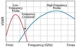
Figure 4 Typical wideband probe response of a passive impedance tuner.
Modern Harmonic Load-Pull Techniques
Harmonic load-pull techniques have existed for decades, since the invention of the earliest closed-loop and open-loop active load-pull techniques between 1979 and 1990.9,10 While state-of-the-art at their time, these systems had inherent stability and processing issues that limited their commercial applications. Throughout the ‘90s and ‘00s, passive mechanical tuners were configured for harmonic load-pull using multiplexers to combine tuners in parallel11 and advanced mathematics to internally/externally cascade tuners in-line.12 As with all passive systems, achievable magnitude of reflection at the DUT was limited by the tuning range of the tuning network and the losses of the components used to connect to the device.
Modern open-loop active load-pull systems were introduced in the ‘00s and ‘10s in order to overcome the weaknesses of the earliest active systems as well as the limitations of purely passive systems.13 Each system, passive harmonic, open-loop active harmonic, hybrid active harmonic and mixed-signal active harmonic has its own strengths and weaknesses, each of which should be clearly understood. The key topics that differentiate the load-pull techniques are measurement method, available magnitude of reflection at the DUT reference, methodology of harmonic control, tuning accuracy and speed, and system cost.
Load-pull systems can be based on scalar or vector measurements of power waves. Scalar-based systems use power meters or spectrum analyzers to measure scalar values at a specified marker or the entire signal, which are then de-embedded to the device reference plane. Vector-based systems use a vector analyzer, calibrated at the DUT reference plane, to directly measure vector a- and b-waves (more accurately, without de-embedding) from which performance parameters are calculated. A two-port network defined by S-parameters and a- and b-waves is shown in Figure 3. While passive load-pull methodologies can be either scalar- or vector-based, active load-pull methodologies require a vector-receiver to measure the a- and b-waves and determine the terminations presented to the DUT.

Figure 5 Maximum reflection of various load-pull methods at the second harmonic (2f0).
Passive impedance tuners are wideband in nature, which means the tuning element (probe/slug) inside the tuner creates a continuum of reflection vectors over a large bandwidth, possibly affecting multiple harmonics, as shown in Figure 4. With a single element, it is possible to control the impedance at one frequency of interest; however, the tuner will present uncontrolled wideband impedances at higher frequencies, including the harmonics. With n tuning elements internally cascaded in a single box or externally cascaded using multiple single-element tuners, it is possible to control the impedance presented at n frequencies. Therefore, a two-element tuner configuration can present controlled impedances at two frequencies, and so on.12
In a traditional scalar harmonic load-pull system comprised of cascaded tuning elements, the maximum magnitude of reflection achievable at any frequency is the summation of the reflections of the elements, minus the losses of the interconnection between the tuners and DUT such that RL(DUT) = RL (tuner) + RL (interconnection). In a typical setup using a 50 ohm test fixture at 2.5 GHz, a realistic |ΓL|=0.93 is achievable at the fundamental frequency while |ΓL|=0.9 is achievable at the second harmonic.
In a modern vector-receiver passive harmonic load-pull system, low-loss couplers are added between the tuner and DUT, thereby increasing the losses (RL interconnection term) and decreasing achievable magnitude of reflection to 0.91 at the fundamental frequency and 0.85 at the second harmonic.
Open-loop active load-pull replaces the passive mechanical tuner with an active tuning chain consisting of a magnitude and phase controllable signal source. Instead of using a passive tuner to reflect energy back to the DUT, the signal source creates a new signal which is injected into the output of the DUT, satisfying ΓL = a2/b2.
In a hybrid active load-pull system using a passive tuner for fundamental impedance control and active tuning chains at the harmonics, realistic |ΓL|=0.86 to 0.91 is achievable at the fundamental frequency while |ΓL|>1 (limited only by injection power) is achievable at the second harmonic.
A purely active load-pull system would have no limits on achievable magnitude of reflection at any frequency so long as the active tuning chain can produce sufficient power to satisfy ΓL = a2/b2.
It is important to note that as frequency increases, the insertion losses of the interconnections generally increase and the tuning range of passive tuning systems decrease. Figure 5 compares the typical magnitudes of reflection achievable at the harmonic frequencies for the various harmonic load-pull methodologies at fo=2.5 GHz.
Active load-pull systems often make use of commercial VNAs which act as both vector-receiver and active tuning chains, depending on the quantity of available signal sources within the instrument. The VNA measures the a- and b-waves presented by the DUT, software calculates the resulting injection signal required to achieve ΓL = a2/b2 at the DUT reference plane and commands the source to create that signal, and the VNA measures the resulting wave at the DUT reference plane for accuracy. An iterative software algorithm adjusts the active injection signal magnitude and phase until the desired reflection is achieved within a predefined convergence limit. The process is repeated for each desired impedance and power.
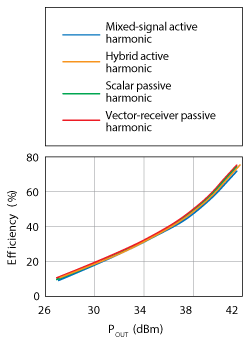
Figure 6 Drain efficiency vs. output power using harmonic load-pull methods with identical loads.
A unique form of active load-pull is referred to as mixed-signal active load-pull (MSALP) and utilizes wideband arbitrary waveform generation with up-conversion, and wideband data analysis with down-conversion, instead of classic active load-pull single frequency generation and analysis methodology. Because of its wideband nature, MSALP uses a time-slotting approach to present many impedances, near-simultaneously, to the DUT, resulting in a much faster tuning and measurement time.13
Regardless of the method used, the same impedances presented at the same frequencies should yield the same measurement results. Figure 6 demonstrates a comparison of measurement results between scalar passive, vector-receiver passive, hybrid active and mixed-signal active harmonic load-pull systems for the same fo, 2fo and 3fo load impedances.
An investigation into the performance of drain efficiency shows that maximum efficiency improvement normally occurs at maximum magnitude of reflection of the harmonic load impedance. In order to yield the highest possible efficiency, a |ΓL| = 1 should be presented at the harmonic frequencies.
Figure 7 shows the change in drain efficiency at 2.5 GHz for a 10 W GaN transistor with varying magnitudes of reflection at a fixed phase of reflection with fixed gain compression and bias. The impact of harmonic tuning increases with its magnitude: presenting a second harmonic termination at |ΓL| = 0.85 (typical of a vector-receiver passive load-pull system) results in a drain efficiency of ~75 percent whereas |ΓL| = 0.99 (possible with active load-pull) results in a drain efficiency of ~80 percent.
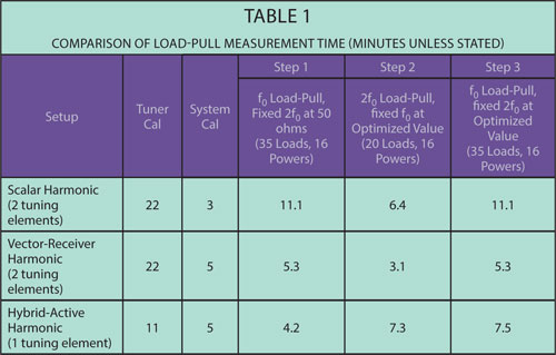
While each technique has different reflection limitations, each technique also has its own characterization, calibration and measurement advantages and disadvantages. In general, using a passive mechanical tuner requires a tuner characterization process, in which S-parameters of a tuning element are mapped into a database for various motor positions. Using n elements results in a time increase by a factor of n. Modern tuners equipped with an LXI™ interface used in conjunction with a modern VNA can be characterized in ~11 minutes per element for 700 to 1000 states, while two single-element tuners or a single two-element tuner requires ~22 minutes for characterization.
System calibration varies between scalar and vector systems. Scalar calibration involves a “power calibration” in which the losses through the input chain are calculated based on de-embedding power meter readings, a process which takes several minutes. Vector-based load-pull calibration is two-fold or three-fold, and involves a vector calibration, an absolute power calibration, and an optional phase calibration for nonlinear VNA measurements. The two-step process takes ~5 minutes while the three-step process takes ~7 minutes.
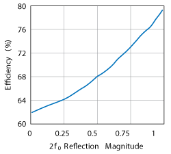
Figure 7 Drain efficiency as a function of 2f0 reflection magnitude at a constant phase.
Tuning time varies between passive and active load-pull methodologies, and the measurement instrument used. Scalar-based, passive load-pull relies on the movement of multiple tuning elements and a slow acquisition with averaging from a power meter. Vector-receiver passive load-pull relies on the same movement of multiple tuning elements; however, the measurement is faster as it uses a vector-receiver in place of the power meter. Traditional open-loop active load-pull measurements can be faster or slower than a passive tuner, depending on the accuracy of the desired tuning and the resulting number of iterations required to converge on the desired impedance (~30 dB tuning accuracy results in faster measurements while ~50 dB tuning accuracy may result in slower measurements). Because mixed-signal active load-pull uses a time-slotting approach with wideband signal generation and analysis, it can present many impedances, near-simultaneously, to the DUT, resulting in a much faster tuning and measurement time.
Table 1 shows the time associated with tuner characterization (if applicable), system calibration, fundamental impedance load-pull with power sweeps for a fixed second harmonic impedance, and second harmonic impedance load-pull with power sweeps for a fixed fundamental impedance. For this comparison, commercial load-pull systems from Maury Microwave were used. The tuners were MT982ML01 LXI?™-certified harmonic tuners; the vector-receiver used was N5242A PNA-X; the active tuning chain consisted of N5242A PNA-X second internal source with an external amplifier; the software used was the MT930-series IVCAD measurement and modeling device characterization suite; the mixed-signal active load-pull system was Maury Microwave’s MT2000.14
Conclusion
It is essential to plan ahead and understand the design objectives and limitations before launching into an extensive and time-consuming design process. With regards to amplifier design, it is important to determine whether the objective is a small-signal linear amplifier, a narrowband highly efficient amplifier or a wideband amplifier, and whether it will use unmatched, partially-matched or fully-matched packaged transistors. Only when the objectives have been defined will it be possible to determine whether the design can or cannot make use of harmonic impedance terminations. If it has been determined that harmonic tuning is required, additional thought must be given to the ideal methodology and technique, evaluating the desired magnitudes of reflection, the equipment that will be dedicated to the load-pull station, and the time allocated to the test and measurement process.
References
- D. M. Pozar, Microwave Engineering, Wiley & Sons, Inc., New York, 2005.
- High Frequency Techniques: An Introduction to RF and Microwave Engineering, Joseph F. White, John Wiley & Sons Inc., 2004.
- P. Colantonio, F. Giannini, R. Giofre and L. Piazzon, “High-Efficiency Ultra-Wideband Power Amplifier in GaN technology,” Electron Letters, Vol. 44, No. 2, pp. 130–131, 2008.
- C. M. Andersson, J. Moon, C. Fager, B. Kim, and N. Rorsman, “Decade Bandwidth High Efficiency GaN HEMT Power Amplifier Designed with Resistive Harmonic Loading,” IEEE MTT-S International Microwave Symposium Digest, June 2012.
- T. Maier, V. Carrubba, R. Quay, F. van Raay, and O. Ambacher, “Active Harmonic Source-/Load-Pull Measurements of AlGaN/GaN HEMTs at X-Band Frequencies,” 83rd ARFTG Microwave Measurement Conference, 2014, pp. 1–4.
- Travis A. Barbieri, Basim Noori “Improvements in High Power LDMOS Amplifier Efficiency Realized Through the Application of Mixed-Signal Active Loadpull,” 82nd ARFTG Microwave Measurement Conference, 2013.
- T. Thrivikraman and J. Hoffman, “Design of an Ultra-High Efficiency GaN High-Power Amplifier for SAR Remote Sensing,” IEEE Aerospace Conference, pp. 1–6, 2013.
- J. Moon, J. Lee, R. Pengelly, R. Baker and B. Kim, “Highly Efficient Saturated Power Amplifier,” IEEE Microwave. Magazine, Vol. 13, No. 1, pp. 125–131, February 2012.
- B. Stancliff and D. P. Poulin, “Harmonic Load-Pull,” MTT-S International Microwave Symposium Digest, pp. 185–187, 1979.
- R. Larose, F. Ghannouchi and R. Bosisio, “A New Multi-harmonic Load-pull Method for Nonlinear Device Characterization and Modeling,” IEEE International Microwave Symposium, pp. 443–446, 1990.
- Maury Microwave, Application Note 5C-053, “A Comparison of Harmonic Tuning Methods for Load Pull Systems.”
- Maury Microwave, Application Note 5C-081, “Cascading Tuners for High VSWR and Harmonic Load Pull.”
- Squillante, M.; Marchetti, M.; Spirito, M.; and de Vreede, L.C.N., “A Mixed-signal Approach for High-Speed Fully Controlled Multidimensional Load-Pull Parameters Sweep,” 73rd ARFTG Microwave Measurement Conference, 2009.
- Maury Microwave website www.maurymw.com/MW_RF/.