
An Internal Integrated Microstrip Antenna for PCS/Cellular Telephones and Other Hand-held Portable Communication Equipment
A compact wideband internal integrated microstrip antenna for personal communications services (PCS) and cellular telephones has been developed. The internal microstrip antenna is extremely rugged and may be integrated into the PCB or plastic case of the telephone. It is also mechanically rigid and reduces the overall size of the telephone. The antenna is sensitive to both vertically and horizontally polarized waves and its radiation patterns have good isotropic characteristics in all the principal planes. The antenna could be easily shielded to reduce interaction between it and the human body. Hence, the device has a very low specific absorption rate (SAR) value and good performance beside the human body as well as in free space. The antenna also may be used in other applications such as digital cordless telephones, pagers, wireless modems and Personal Computer Memory Card International Association (PCMCIA) pager cards.
Mohamed Sanad and Noha Hassan
AMANT
Reno, NV
Portable wireless communication equipment such as cordless, PCS and cellular telephones; pagers; wireless modems; and PCMCIA pager cards are required to operate properly beside the human body and/or inside portable computers and free space. Usually, this equipment is hand held and orientated randomly by the operator. As a result, the antennas are required to be small, lightweight and sensitive to two perpendicular polarizations. The radiation patterns must be quasi-isotropic in all the principal planes and, in many applications, should have a wide frequency bandwidth. The effect of the human body on the antenna as well as the SAR of the radiation from the antenna by the human body must be as small as possible. Furthermore, in portable wireless communication equipment, it is always desirable to integrate the antenna into the PCB or plastic case.
External wire antennas, which traditionally are extendible (such as monopoles and helical antennas), usually are used with portable wireless communication equipment, especially PCS and cellular telephones. However, these external wire antennas have many disadvantages. External wire antennas cannot be integrated into the PCB or plastic case. They increase the total size of the telephone (especially if they are retractable) and are easy to break or bend. The effect of the human body on external antennas is significant because the antennas have high SAR values and are not easy to shield. They are sensitive only to one polarization and offer poor electrical performance in the field next to the human body. External antennas, especially helical antennas, are difficult to manufacture in an accurate, repeatable way and require a matching circuit (which increases cost and losses). Furthermore, the physical contact between retractable antennas and the telephone is affected by how many times the retractable antenna has been extended.
In addition, with retractable antennas, there is a middle position in which the retractable antenna is not connected electrically to the telephone. Actually, many customers use the telephone while the retractable antenna is in this middle, disconnected position. Moreover, external antennas require an internal diversity antenna to solve fading problems. On the other hand, it is difficult to separate receive and transmit bands of the external antenna to eliminate the duplexer or at least make it easy to design. It is also difficult to design an efficient dual-band external antenna for PCS and cellular telephones.
PCS/Cellular Telephone External Wire Antenna Evaluation
Figure 1 shows the free-space 840 MHz vertically and horizontally polarized radiation patterns in the principal planes of a conventional helical antenna, which is mounted on a cellular telephone and vertically orientated. As shown, the helical antenna is sensitive only to one polarization while its sensitivity to the other polarization is poor. In the horizontal plane, the efficiency of the vertically polarized waves is approximately 70 percent while the efficiency of the horizontally polarized waves is less than five percent. In the vertical plane, the horizontally polarized radiation pattern of the cellular telephone external helical antenna still is poor and even the vertically polarized pattern has two deep nulls and is not satisfactory. Since cellular base station antennas are vertically polarized, the highest possible sensitivity that may be obtained from the cellular handset exists in the horizontal plane when the telephone is vertically orientated in free space. Actually, this configuration is the method used by most cellular telephone companies to measure the sensitivity of their cellular telephones. Thus, they evaluate the performance of their cellular telephone antennas in their best environment and orientation in the optimum plane.
The radiation patterns of the same cellular telephone external helical antenna also were measured while the cellular telephone was held beside the head of a human body. In this case, the efficiency of the antenna is approximately 10 percent.1 Thus, the overall efficiency of the cellular telephone external helical antenna is reduced considerably next to the human body. This power loss is due to the absorption of electromagnetic waves by the human head and hand, and the mismatch of the antenna beside the human body. An accurate measurement of the ratio of power loss due to each of these two factors is not easy. However, this ratio can be roughly estimated by measuring the return loss of the antenna in free space and beside the human body. Power loss due to the mismatch of the antenna beside the human body was determined to be approximately 20 percent of the total power loss. Hence, approximately 80 percent of the power loss beside the human body is absorbed by the human head and hand. A larger difference between the radiation patterns of the antenna in free space and beside the human body means more power absorption by the human body, higher SAR values and more difficulties in passing the FCC requirements. However, the effect of the human body on the antenna differs from one person to another. In addition, it depends on the way the operator holds the cellular telephone next to his or her ear. In order to ensure the repeatability of these measurements, it is better to use a model to simulate the human head and hand instead of an actual human body.
From this analysis, it is clear that the performance of PCS and cellular telephone antennas should be evaluated beside a human body or a model. Unfortunately, most of the antenna companies and cellular telephone companies evaluate their antennas only in free space. These companies measure the antennas' sensitivity to the vertically polarized waves in the horizontal plane and prefer the antenna that has the highest sensitivity to this polarization. It may not be easy to convince cellular telephone companies to change their way of evaluating antennas. Instead, antenna designers should concentrate on designing better cellular telephone antennas that perform well in free space and beside the human body. The effect of the human body on the antenna as well as the effect of the antenna on the human body must be as small as possible. Many factors can help reduce the interaction between the antenna and human body. The first important factor is the choice of the correct antenna design. Unfortunately, none of the existing conventional cellular telephone external antennas (such as helical or monopulse antennas) performs well beside the human body.
Internal Integrated Microstrip Antenna Advantages
Internal microstrip antennas may be integrated into the PCB or plastic case of the telephone. These antennas are mechanically rigid and difficult to break. They are fixed inside the telephone and, thus, do not increase its overall size. Customers are not required to extend these internal antennas while using the telephone and, hence, are not affected by using the telephone. Furthermore, a high level of shielding technology may be used to shield the internal antenna such that it has a negligible SAR value and is affected only minorly by the human body.
Probably the most promising technique to significantly reduce the interaction between the cellular telephone antenna and the human body is to use an internal integrated antenna such as a microstrip antenna. Microstrip antennas are considered one of the best candidates for such applications because they provide 50 W input impedance and, thus, do not require a matching circuit or balun. Microstrip antennas are relatively easy to manufacture accurately and repeatably. Furthermore, microstrip antennas may be fed by coupling and, thus, eliminate physical contact between the antenna and the RF circuit. Moreover, it is relatively easy to separate the receive and transmit bands of microstrip antennas to eliminate the duplexer or at least make it easy to design. It is also relatively easy to design dual-band internal integrated microstrip antennas for PCS and cellular telephones. On the other hand, internal integrated microstrip antennas may use the E- and H-field components diversity technique, which does not require an additional separate diversity antenna.2
Internal Integrated Microstrip Antenna Design Parameters
Conventional microstrip antennas do not fulfill many of the requirements of small-size, hand-held portable wireless communication equipment. However, these antennas have many design parameters that could be optimized to reduce their size and cost, increase their bandwidth, make them sensitive to both vertically and horizontally polarized waves, improve their isotropic radiation characteristics and reduce their interaction with the human body. In this research, all possible techniques and modifications to the conventional microstrip antenna to meet such requirements have been studied.
The first well-known technique to reduce the size of the conventional half-wavelength microstrip antenna by approximately 50 percent is to short-circuit its zero potential plane. A partially shorted microstrip antenna is used to further reduce the size of the shorted quarter-wavelength antenna. In this case, only a small portion of the zero potential plane is short-circuited instead of shorting the entire plane.3 In mass production, the partially shorted microstrip antenna has poor manufacturing repeatability. Therefore, the partial short circuit must be simulated and replaced by shorting posts. The number and dimensions of these shorting posts have a considerable effect on the resonant frequency of the partially shorted microstrip antenna. Reducing the diameter and/or number of the shorting posts reduces the resonant frequency of the antenna.4
One of the most important design parameters is the size of the microstrip antenna's ground plane. Truncating the ground plane reduces the size of the antenna and improves its isotropic characteristics, sensitivity to two perpendicular polarizations and performance beside the human body.5 However, truncating the ground plane beside the radiating edge of conventional microstrip antenna geometries reduces their efficiency considerably. Therefore, nonconventional configurations must be used such as double C-patch microstrip antennas.6 The geometry of the antenna has a considerable effect on both the size and performance of the antenna, especially beside the human body.7 Furthermore, using nonconventional microstrip antenna geometries increases the number of design parameters that may be utilized to optimize the characteristics of the antenna.
 The conventional way to improve the microstrip antenna's bandwidth is to increase its thickness substantially or to use either planar or nonplanar stacked parasitic elements. However, these techniques increase the antenna's size significantly. Both the length and width of the driven element and each parasitic element usually range from a half-wavelength to a quarter-wavelength. In this research, a compact
 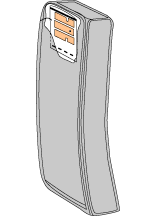 wideband microstrip antenna for PCS and cellular telephones has been developed.8 In these designs, a compact narrow driven element has been combined with both planar and stacked compact narrow parasitic elements that have different geometries, as shown in Figure 2 . Different configurations and combinations of such microstrip antenna geometries have been designed, optimized, manufactured, and installed and tested inside several PCS and cellular telephones, as shown in Figure 3 .
 With a dielectric constant of approximately 6, the total size of the preferred cellular telephone microstrip antenna configuration is 30 x 30 x 3 mm while the total size of the PCS antenna is approximately 15.0 x 15.0 x 1.5 mm. Figure 4 shows the return loss and input impedance of an internal integrated cellular telephone microstrip antenna configuration. The driven element is a C-patch with a triangular aperture shape; each parasitic element is a C-patch with a rectangular aperture shape. With a return loss of approximately -10 dB, the frequency bandwidth is approximately 74
 MHz at 860 MHz. Hence, the bandwidth of the microstrip antenna is 8.5 percent, which covers the entire cellular band. The input impedance of the antenna is approximately 50 W and, thus, does not require a matching circuit or balun and may be connected directly to the duplexer. Figure 5 shows the antenna's vertically and horizontally polarized radiation patterns in the principal planes. It is clear that the radiation patterns are quasi-isotropic and the antenna is sensitive to vertically and horizontally polarized waves in both principal planes.
Many configurations of similarly developed PCS and cellular telephone internal integrated microstrip antennas have been tested in the anechoic chamber and field trial, in free space and beside the human body. It was determined that the interaction between the human body and these developed internal integrated microstrip antennas is much smaller than the interaction between the human body and external wire antennas such as monopoles and helical antennas.1 In the field trial, the performance of the cellular telephone with an internal integrated microstrip antenna was consistently better than its performance with an external wire antenna.
Other Internal Integrated Microstrip Antenna Applications
The developed internal microstrip antenna also was installed inside the handset and base station of several digital cordless telephones operating at 900 MHz to replace their external whips and sleeve dipoles. These digital cordless telephones require a bandwidth of less than four percent at 900 MHz, which is less than half the bandwidth of cellular telephones. The size of the internal cordless telephone microstrip antenna is approximately 30 x 30 x 2 mm.
The radiation patterns of the developed microstrip antenna installed inside the  handset or base station of a digital cordless telephone are very similar to those of the cellular telephone internal microstrip antenna shown previously and, therefore, are not presented here. The coverage distances of these digital cordless telephones were measured in field trials with both internal and external antennas. Figure 6 shows the input impedance and return loss of the digital cordless telephone's integrated microstrip antenna. The coverage distance is defined as the maximum distance between the handset and base station in which the telephone voice is still clear. This distance was determined using the low signal or out-of-range indicators, which are included in most digital cordless telephones. These field trials were repeated in different environments inside and outside several buildings and in different areas, including metropolitan areas. The performance of the internal microstrip antenna was good even when the telephone's handset was held next to the operator's head. The coverage distances of the digital cordless telephones with internal microstrip antennas were consistently double the coverage distances achieved using external wire antennas.
The developed microstrip antenna also was integrated into PCMCIA communication cards and wireless modems. PCMCIA cards are small form factor adapters for personal computers, personal communications equipment or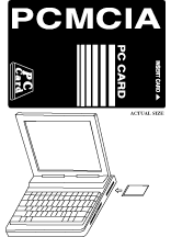 other electronic devices.9 The cards are approximately the same size and shape of a credit card and can be used with any personal portable computer system equipped with a PCMCIA slot. Typically, these PCMCIA cards are used for memory enhancements and/or input/output features such as wireless modems, local area networks and host communications. Figure 7 shows a pager card that fits a PCMCIA type II slot and supports all 900 MHz paging carrier services in the US. The card is designed to provide messaging capability to laptops, notebooks, palmtops and other portable computer systems. The card also operates as a stand-alone pager when it is not connected to a computer. Since these pagers also may be hand held or used in an operator's pocket, their antennas must have a negligible human body effect. Furthermore, these antennas must have approximately the same resonant frequency, input impedance and radiation patterns in free space as inside a PCMCIA type II slot in a portable computer.
Some of the PCMCIA communication cards require a wide bandwidth similar to  that of cellular or digital cordless telephones while some require a very narrow bandwidth of less than one percent at 900 MHz, depending on the application. The developed integrated microstrip antenna may be used in both cases. The size of the developed narrowband PCMCIA card internal microstrip antenna is approximately 30 x 30 x 1 mm. Figure 8 shows the return loss and input impedance of the narrowband microstrip antenna contained in a PCMCIA pager card while the pager card was inside or outside the PCMCIA slot of a palmtop computer. It is clear that inserting the antenna inside the PCMCIA slot has a negligible effect on the resonant frequency and return loss of the antenna.
The radiation patterns of the PCMCIA pager card internal integrated microstrip antenna were measured in different situations. The measured patterns of the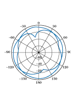 antenna in the horizontal plane while the pager card was inside a hand-held palmtop computer are shown in Figure 9 . This condition, where the PCMCIA card is inserted inside the PCMCIA slot of a palmtop computer while the computer is held by the operator, is the worst possible situation that this antenna must face. The radiation patterns are still quasi-isometric and sensitive to both vertically and horizontally polarized waves. Furthermore, the performance of the antenna inside the PCMCIA slot beside the human body is good. The horizontal plane is the most important one to consider, especially if the pager card is operating inside the PCMCIA slot in a personal computer, because personal computers usually operate in a horizontal position. The performance of the PCMCIA pager card with an internal integrated microstrip antenna also was tested in the field trial and performed consistently better than similar PCMCIA pager cards with external wire antennas (usually loop antennas).
Conclusion
A compact wideband internal integrated microstrip antenna for PCS and cellular telephones has been developed. With a dielectric constant of approximately 6, the size of the cellular telephone antenna is 30 x 30 x 3 mm and the size of the PCS antenna is 15.0 x 15.0 x 1.5 mm. The antenna is sensitive to both vertically and horizontally polarized waves with good radiation pattern characteristics in all the principal planes, in free space as well as next to the human body. The interaction between the antenna and the human body was determined to be less than the interaction between the human body and typical cellular telephone external wire antennas. The developed antenna also may be integrated into digital cordless telephones, PCMCIA pager cards and wireless modems. The size of the digital cordless telephone internal integrated microstrip antenna is approximately 30 x 30 x 2 mm while the size of the PCMCIA pager card antenna is approximately 30 x 30 x 1 mm.
The internal integrated microstrip antenna is a relatively new technology and has many design parameters that may be optimized to fulfill the portable wireless communication requirements. For example, it is relatively easy to design a dual-band internal integrated microstrip antenna for PCS and cellular telephones. In addition, it is possible to isolate both the receive and transmit bands of the internal microstrip antenna to eliminate the duplexer or, at least, simplify its design. Furthermore, internal integrated microstrip antennas are relatively easy to shield and some configurations do not require a separate diversity antenna. Most of these issues still require additional scientific research.
References
1. Mohamed Sanad and Noha Hassan, "Evaluation of Cellular Phone Antennas and the Advantages of Using Internal Antennas," Proceedings of the IEEE AP-S Symposium, Atlanta, GA, June 1998.
2. W. Lee, "Statistical Analysis of the Level Crossings and Duration of Fades of the Signal from an Energy Density Mobile Radio Antenna," Bell System Technical Journal, Vol. 46, February 1967, pp. 416-440.
3. Mohamed Sanad, "A Small Size Microstrip Antenna Having a Partial Short Circuit," Proceedings of the IEE ICAP '95, The Netherlands, April 1995, pp. 282-285.
4. Mohamed Sanad, "Effect of the Shorting Posts on Short Circuit Microstrip Antennas," Proceedings of the IEEE AP-S Symposium, University of Washington, Seattle, June 1994, pp. 794-797.
5. Mohamed Sanad, "Microstrip Antennas on Very Small Ground Planes for Portable Communication Systems," Proceedings of the IEEE AP-S Symposium, Seattle, WA, June 1994, pp. 810-813.
6. Mohamed Sanad, "Double C-patch Antennas Having Different Aperture Shapes," Proceedings of the IEEE AP-S Symposium, Newport Beach, CA, June 1995, pp. 2116-2119.
7. Mohamed Sanad, "Effect of Microstrip Antennas on the Human Body," Proceedings of the IEEE AP-S Symposium, Seattle, WA, June 1994, pp. 298-301.
8. Mohamed Sanad, "A Compact Broadband Microstrip Antenna for Portable Communication Equipment," US Patent Application No. 60/042,275, February 1997.
9. J. Greenup, "PCMCIA 2 Contains Support to I/O Cards, Peripheral Expansion," Computer Technology Review, US, 1992, pp. 43-48.