
This third article in the series on metamaterial Möbius strip resonators addresses their use in signal sources for test and measurement equipment and wireless communications systems. The resonators enable tunable, multi-band oscillators with smaller size and lower power consumption compared to separate oscillators for each band. The signal sources described in this article demonstrate significant improvements in figure-of-merit (FOM) for a given phase noise, tuning range, power consumption, size and cost. With MMIC fabrication techniques and the broad application of this artificial material, metamaterial technology offers promising planar voltage-controlled oscillator (VCO) solutions for microwave frequencies.

Modern communications systems require compact signal sources with low phase noise. For decades, design engineers have been improving phase noise and broadband tuning to satisfy the evolving performance requirements that modern communication systems are demanding. This development has followed two distinct paths: reducing the size of the printed resonator without degrading the quality factor and improving oscillator circuit topologies to improve FOM.
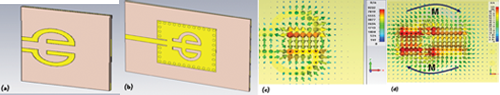
Figure 1 The microstrip coupled-line resonator (a) and complementary coupled resonator (b). The coupled-line resonator's electric field distribution and electric current flow with differential excitation (c). The magnetic field distribution and equivalent magnetic current flow of the complementary coupled resonator (d). Results from a collabroation between Synergy Microwave and Prof. Tatsuo Itoh of UCLA33.
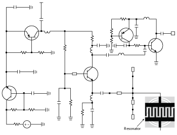
Figure 2 Schematic of a 3.85 GHz oscillator using an evanescent-mode coupled metamaterial resonator (patent pending).30
A spot phase noise (PN) number is misleading when comparing oscillators, unless they are at the same frequency offset from the carrier for a given tuning range and output power. To compare oscillators operating at different frequencies, tuning ranges and output power levels, a single number FOM has long been desired. Two metrics being used are a FOM, in dBc/Hz, and power frequency tuning normalized (PFTN), in dB, defined as1,28

where f0 is the oscillation frequency, L(foffset) is the phase noise at the offset frequency foffset, k is the Boltzmann constant, Δf = fmax - fmin or the tuning range, T is temperature in Kelvin, and PDC is the total consumed DC power in mW. The larger the |FOM| and PFTN values, the better the oscillator.
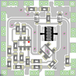
Figure 3 Layout of the oscillator (patent pending).
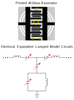
Figure 4 Layout of the metamaterial Möbius resonator with varactor diodes used for tuning (top) with lumped-circuit model (bottom).30
PFTN is a critical requirement for multi-band tunable oscillators. The other important requirement is DC to RF conversion efficiency. From equations 1 and 2, the FOM for integrated phase noise, in dBc, from 1 kHz to 1 MHz is given by

Figure 5 Simulated spectrum showing the harmonic rejection achieved with evanescent-mode coupling.

where: Δf = fmax – fmin; fmax = maximum oscillation frequency; fmin = minimum oscillation frequency; P2(Φ) = integrated phase noise from 1 kHz to 1 MHz; PRF = signal output power averaged over frequency; PDC = DC power consumption of the oscillator.
A compact, high Q-factor resonator is key to obtaining the best FOMs. Toward this goal, substrate integrated waveguides (SIW) are attractive because of their waveguide-like performance and compatibility with planar printed circuit board (PCB) technology.2 Cavities based on SIWs are an excellent choice for oscillator resonators, since they have high Qs and low loss. Several tunable or switchable SIW resonators have recently been reported.3-5 Tuning or switching is achieved by connecting a varactor or PIN diode to a floating metal pad on the top of the SIW cavity, using bond wires. However, this creates unwanted radiation loss and reduces the Q, because of the closed-loop slots surrounding the floating metal. Also, the bond wires used for DC bias increase the fabrication complexity and may introduce parasitics.

Figure 6 Simulated phase noise plots showing 15 dB improvement from evanescent-mode coupling.
The novel evanescent-mode metamaterial resonator enables the design of oscillators with improved phase noise and FOM compared to other published results. Table 1 shows the performance of state-of-the-art VCOs that use various fabrication technologies. The metamaterial designs described in this article achieve superior FOM and PFTN for a given class, topology and bill of materials (BOM).
NEGATIVE INDEX PRINTED RESONATOR
The negative index printed resonator is a key component for the design of oscillator circuits at microwave and millimeter wave frequencies. Originally proposed by John Pendry, a typical printed split ring resonator (SRR) is a sub-wavelength resonator that inhibits signal propagation in a narrow band in the vicinity of its resonant frequency, provided the magnetic field is polarized along the axis of the ring.24-26
Recently, a new type of tunable resonator was reported based on complementary coupled resonators (CCR) using SIW technologies.27-33 The proposed CCR is essentially a complementary version of a conventional microstrip coupled-line resonator. Figure 1a shows the typical geometry of the conventional coupled-line resonator, Figure 1b the equivalent complementary structure. The electric field and current flow of the coupled-line resonator with differential excitation is shown in Figure 1c. Using the principle of duality, the coupling mechanism for the complementary coupled resonator is through the magnetic field, shown in Figure 1d, which has a distribution similar to the electric field in the conventional coupled-line resonator.
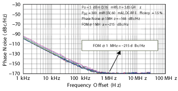
Figure 7 Measured phase noise of the 3.85 GHz oscillator.
In the conventional coupled resonator, the differential mode needs to be excited by a pair of inputs with opposite polarity. However the complementary coupled resonator is normally excited in a differential mode due to the nature of the fundamental mode in the waveguide. The equivalent magnetic currents on the slots of the complementary coupled resonator flow in opposite directions at the symmetrically opposite edges on the SIW resonator, minimizing radiation and yielding a high Q-factor.
The Q-factors of one and two-port resonators are given by33

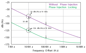
Figure 8 Simulated phase noise of the evanescent-mode phase-injection locked oscillator. Phase injection locked improves the noise floor by 50 dB.
where Z21 (ω0) and Z21 (ω0)’ signify the impedance and its derivative, respectively, of the SIW resonator structure at frequency ω0.
The drawback of the CCR structure is its limited tuning range. A possible way for improving the tuning of the CRR topology is to use negative index material in conjunction with evanescent-mode coupling. Negative index material, broadly known as left-handed (LH), has a negative refractive index.30

where n is the refractive index of the medium, εo = 8.85 × 10⁻¹² and µ0 = 4π × 10-7.
The sign of permittivity and permeability in equation 6 is not restricted by any physical law and can be positive or negative. Negative refractive index material has anti-parallel phase and group velocities, which allows an electromagnetic wave to convey energy and group velocity in the opposite direction to its phase velocity. This causes strong localization and enhancement of the fields, significantly enhancing the quality factor of resonators.
In the remainder of this article, several examples of oscillator circuits using Möbius metamaterials are shown. The designs are targeted to replace competing high Q technologies such as surface acoustic wave (SAW), bulk acoustic wave (BAW), surface transverse wave (STW), whisper gallery mode (WGM), ceramic and dielectric resonators.
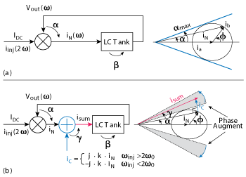
Figure 9 Oscillator block diagram and phasor diagram for an oscillator without phase-injection (a) and with phase-injection (b).24
As discussed in the prior two articles (November and December, 2014), the manipulation of evanescent mode coupling enables the Q of the resonator to be multiplied and used for high performance tunable oscillators. The Q multiplier effect does not violate energy conservation because the evanescent mode only stores and does not transport the energy.
Metamaterial Möbius strip resonators have several advantages compared with conventional planar resonators:30
- High Q-factor and improved selectivity
- Easy integration in MIC/MMIC technologies
- Small dimensions and weight
- Multi-band characteristics
- Relative insensitivity to electromagnetic interference
3.85 GHz EVANESCENT-MODE METAMATERIAL MÖBIUS RESONATOR OSCILLATOR
The schematic of a fixed 3.85 GHz oscillator is shown in Figure 2 and the board layout in Figure 3. The design uses a SiGe transistor as the active device and a 20 mil thick substrate, with a dielectric constant of 2.2, for the microstrip and stripline matching circuits and interconnects. Figure 4 provides a close-up view of the metamaterial Möbius strip resonator with varactor diodes that are used for tuning; the equivalent circuit of the resonator structure is shown on the right.32
The oscillator is biased at 5 V DC and consumes 60 mA; the measured output power exceeds 5 dBm. Figure 5 is a plot of the simulated output spectrum, showing that evanescent mode coupling improves the second and third harmonic rejection by more than 33 and 55 dB, respectively. The simulated phase noise (see Figure 6) also shows the effect of evanescent-mode coupling, which improves the noise performance by 15 dB. The measured phase noise (see Figure 7) indicates that 5 to 8 dB of the 15 dB predicted improvement is realized, depending upon of the level of evanescent-mode coupling. The FOM for the oscillator is -215 dBc/Hz.

Figure 10 Oscillator circuit dynamics, showing the limit cycle (a) dψ/dt versus ψ (b) and phase shift due to impulse perturbation at φi.24
The varactor diodes incorporated in the Möbius resonator improve the tuning, but the oscillator is susceptible to mode jumping, since the resonator structure exhibits both series and parallel resonance. To ensure reliable and stable operation, the higher order modes are suppressed using a phase-injection locking mechanism.
7 GHz EMPIMC RESONATOR BASED OSCILLATOR
The evanescent-mode phase-injection mode-coupled (EMPIMC) oscillator significantly improves phase noise performance, as shown by the simulation in Figure 8. The basic oscillator without phase-injection consists of an analog mixer feeding an LC tank with finite Q-factor and a feedback loop from the output to the mixer, as shown in the block diagram of Figure 9a. To maintain stable oscillation, the loop gain should be greater than unity, and the total phase shift must be zero. The loop gain condition is easily satisfied, but the phase shift condition limits the locking range.24 Considering the phase shift introduced by the LC tank at frequency ω is β, the mixer is required to introduce another phase shift α so that α+ β= 0. By incorporating additional phase shift, γ, after the mixer, the locking range can be increased (see Figure 9b).
The locking condition is described by

From equation 7, the locking range is restricted by the maximum phase shift that the mixer can provide and is described by

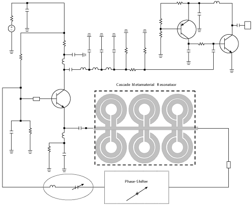
Figure 11 Oscillator schematic, showing the cascaded metamaterial resonator (patent pending).
where f0 is the resonant frequency, Q is the quality factor of the LC tank and η is the injection ratio (iinj/IDC). The Q-factor is given by34
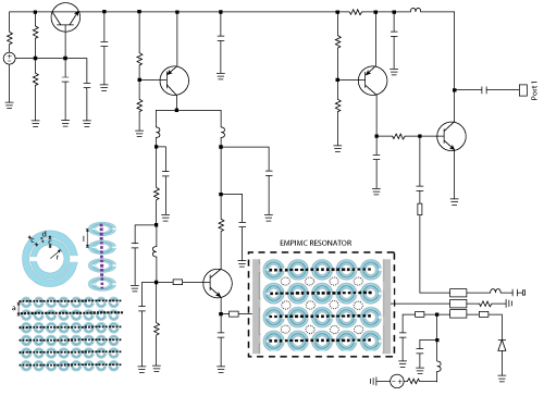
Figure 12 Schematic of a tunable oscillator using a two-dimensional cascaded injection-locked metamaterial resonator network (patent pending).
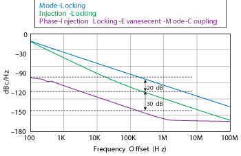
Figure 13 Simulated phase noise of the tuned metamaterial oscillator. Phase-injection locking improves the phase noise by 30 dB.

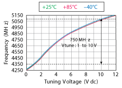
Figure 14 Tuning characteristics of the oscillator.
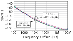
Figure 15 Measured phase noise of the evanescent-mode phase-injection locking oscillator.
where j(ω) is the phase of the oscillator’s open loop transfer function at steady state, and τd is the group delay of the resonator. From equation 9, QL is proportional to the group delay; therefore, for low phase noise, the design goal is to maximize the group delay of the Möbius strip resonator by incorporating phase-injection techniques. The unique characteristic of the Möbius strip is self phase-injection along the mutually-coupled surface of the strips, which enables higher Q-factor for a given size of the printed transmission line resonator.30
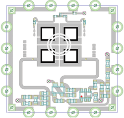
Figure 16 Board layout of the X-Band oscillator (patent pending).
By incorporating additional phase shift Υ= tan-1 (|iC|/|iN) after the mixer module, as shown in Figure 9b, the locking range can be increased and is described by24

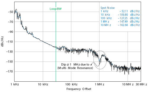
Figure 17 Measured phase noise of the X-Band oscillator showing jumping phenomenon at 1 MHz offset.
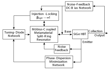
Figure 18 Block diagram of the mode-stabilized oscillator design.
where m is the coupling strength. Figure 10 shows the typical oscillator circuit dynamics for enabling phase-injection and improving the locking range.
An objective of this design was to improve the Q of the metamaterial resonator by cascading a progressive-wave evanescent mode-coupled resonating network (shown in the schematic of Figure 11) to lower the phase noise without compromising the tuning range. Phase-injection locking improves the oscillator’s phase noise by 50 dB (see Figure 8). Cascading resonators improves the Q of the overall resonator, because the sharp change in permittivity and permeability at resonance causes a significant increase in the group delay, multiplying the Q. However, one must be careful to avoid or suppress the degeneration modes, which limits the application to below 20 GHz.
The Q-factor of a conventional LC or printed resonator at a given frequency is independent of the current through the resonator, described by

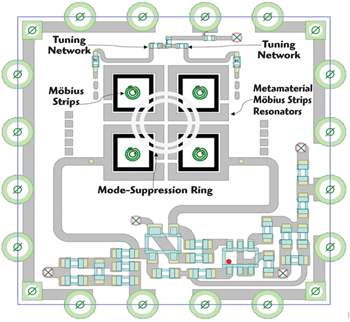
Figure 19 Board layout of the mode-stabilized VCO showing the Möbius strips and mode suppression ring.
where Φ(ω) is the phase of the resonator impedance.
Unlike passive LC resonators, the effective inductance of the metamaterial resonator varies with current and voltage, so this definition of Q is not valid. Accounting for the variation in permittivity and permeability of a metamaterial resonator, the Q is given by30

where Imin and Imax are the minimum and maximum currents, and Qa(ω,i) is the instantaneous quality factor at frequency ω and current i. This equation enables the calculation of the Q-factor of a metamaterial resonator when the resonator operates in negative permeability (µ < 0) or negative permittivity (ε< 0) conditions.
TUNABLE EMPIMC RESONATOR BASED OSCILLATORS
The schematic of a tunable oscillator using evanescent-mode phase-injection mode coupling is shown in Figure 12. The simulated phase noise is plotted in Figure 13. The oscillator covers 4.25 to 5.1 GHz with a tuning voltage from 0 to 12 V (see Figure 14) and delivers a typical output power of 3 dBm. The design is biased at 5V and consumes 80 mA. As simulated, evanescent-mode phase-injection locking improves oscillator phase noise by 30 dB compared with injection-locking. The measured phase noise is plotted in Figure 15. At 10 kHz offset, the phase noise ranges from -118 dBc/Hz at 4.2 GHz to -112 dBc/Hz at 5.2 GHz.
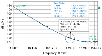
Figure 20 Measured phase noise of the X-Band oscillator after mode stabilizing the design. The noise floor has been significantly improved, with no jumping at 1 MHz offset.
X-BAND TUNABLE EMPIMC RESONATOR OSCILLATOR
An oscillator using a novel mode-locked evanescent-mode metamaterial resonator was developed to provide a tunable signal source for X-Band radar applications. The design uses SiGe HBTs as the active stages and provides 5 dBm output power, drawing 30 mA at 10 V bias. The oscillator is assembled on a 20 mil board with a dielectric constant of 2.2 (see Figure 16).
The phase noise of the design, shown in Figure 17, exhibits a hump and dip at around 1 MHz offset. This reflects the resonator mode jumping phenomena or, possibly, phase-injection from the measurement equipment. To overcome mode-jumping and tuning problems, mode stabilization is incorporated into the design by introducing a mode-suppression ring that allows multi-mode self-injection into the Möbius strip cavity. A block diagram of the design is shown in Figure 18, with the board layout in Figure 19. Figure 20 plots the measured phase noise of the new design, which has significantly lower phase noise and no hump or dip at 1 MHz offset.
TUNABLE MULTI-BAND OSCILLATORS
The concept of evanescent-mode Möbius metamaterial resonator oscillators can be utilized to make compact, tunable, multi-band oscillators that cannot be achieved with conventional printed transmission line resonators. As an example, a tunable oscillator was developed covering four bands: 2 to 2.5, 2.5 to 3, 3 to 3.5 and 3.5 to 4 GHz. It provides a cost-effective alternative to traditional VCOs for wireless applications.
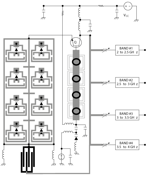
Figure 21 Simplified schematic of tunable multi-band oscillator design using evanescent-mode metamaterial resonator network (patent pending).
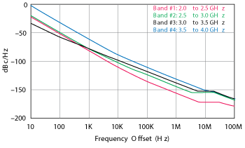
Figure 22 Simulated phase noise of the multi-band VCO design, designed to cover 2 to 4 GHz.
A simplified circuit schematic is shown in Figure 21. Fourth-order, evanescent-mode metamaterial resonators are used to generate the four multi-band frequencies without multipliers or switching among resonators and oscillators. This approach reduces the complexity, size and power consumption of the oscillator, compared with other methods, and achieves excellent phase-noise performance. The multiple-band oscillator requires only 20 mA at 5 V bias and delivers 3 dBm typical output power. The simulated phase noise is better than -130 dBc/Hz at 1 MHz offset for any of the four bands, as shown in Figure 22. The measured phase noise (see Figure 23) agrees with the simulations within 3 to 5 dB.
CONCLUSION
Möbius metamaterial technology is a promising alternative to high frequency planar VCO solutions for radio communication systems, enabled by the development of MMIC fabrication techniques and the broad application of this artificial material. As shown in Table 1, the VCO designs presented in this article show superior FOM and PFTN performance for a given class, topology and BOM.
As stated throughout this series, the Möbius strip has captured the imaginations of mathematicians and engineers since it was discovered. Its non-orientability and one-sidedness continue to intrigue. Even as applications like conveyor belts with twice the lifespan of non-twisted belts fade out of use, new applications of the Möbius strip, such as the Möbius resistor, are discovered. The Möbius strip will continue to appear, both as a novelty mathematical figure and an essential component in inventions, recurring in an endless – one could even say Möbius – loop.
References
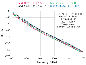
Figure 23 Measured phase noise of the multi-band VCO design covering 2 to 4 GHz.
- D. Hamand and A. Hajimiri, “Concepts and Methods in Optimization of Integrated LC VCOs,” IEEE Journal of Solid-State Circuits, Vol. 36, No. 6, pp. 896–909, June 2001.
- F. Xu and K. Wu, “Guided-Wave and Leakage Characteristics of Substrate Integrated Waveguide,” IEEE Transactions Microwave Theory & Techniques, Vol. 53, No. 1, pp. 66–73, January 2005.
- Y. Dong and T. Itoh, “A Dual-Band Oscillator with Reconfigurable Cavity-Backed Complementary Split-Ring Resonator,” IEEE MTT-S International Digest, June 17–22, 2012, pp. 1–3.
- F. F. He, K. Wu, W. Hong, L. Ha and X. Chen, “A Low Phase-Noise VCO Using an Electronically Tunable Substrate Integrated Waveguide Resonator,” IEEE Transactions Microwave Theory & Techniques, Vol. 58, No. 12, pp. 3452–3458, December 2010.
- S. Sirci, J. D. Martinez, M. Taroncher and V. E. Boria, “Varactor Loaded Continuously Tunable SIW Resonator for Reconfigurable Filter Design,” Proceedings 41st European Microwave Conference, 2011, pp. 436–439.
- D. Ozis, N. M. Neihart and D. J. Allstot, “Differential VCO and Passive Frequency Doubler in 0.18 mm CMOS for 24 GHz Applications,” IEEE RF IC Symposium Digest, 2006.
- S. Ko, J. G. Kim, T. Song, E. Yoom and S. Hong, “20 GHz Integrated CMOS Frequency Sources with a Quadrature VCO Using Transformers,” IEEE RF IC Symposium Digest, 2004.
- H.H. Hsieh and L.H. Lu, “A Low-Phase-Noise K-Band CMOS VCO,” IEEE MWCL, Vol. 16, No. 10, pp. 552–554, October 2006.
- C. M. Yang, H. L. Kao, Y. C. Chang and M. T. Chen, “A Low Phase Noise 20 GHz Voltage Control Oscillator Using 0.18 µm CMOS Technology,” IEEE DDECS, pp. 185–188, 2010.
- Chien et. al., “40 GHz Wide-Locking-Range Regenerative Frequency Divider and Low-Phase-Noise Balanced VCO in 0.18 µm CMOS,” IEEE International SSC Conference Technical Digest, February 2007, pp. 544–545.
- Y. Wachi, T. Nagasaku and H. Kondoh, “A 28 GHz Low-Phase-Noise CMOS VCO Using an Amplitude Redistribution Technique,” IEEE International SSCF Tech. Digest, February 2008, pp. 482–483.
- H.Y. Chang and Y.T. Chiu, “K-Band CMOS Differential and Quadrature Voltage-Controlled Oscillators for Low-Phase-Noise and Low-Power Applications,” IEEE Transactions Microwave Theory Techniques, Vol. 60, No. 1, pp. 46–59, January 2012.
- T.P. Wang, “A K-Band Low-Power Colpitts VCO with Voltage-to-Current Positive-Feedback Network in 0.18 µm CMOS,” IEEE MWCL,Vol. 21, No. 4, pp. 218–220, April 2011.
- Liu et al., “A Low-Power-Band CMOS VCO with Four-Coil Transformer Feedback,” IEEE MWC, Vol. 20, pp. 459–461, 2010.
- J. Kim et al., “A 44 GHz Differentially Tuned VCO With 4 GHz Tuning Range in 0.12 m SOI CMOS,” IEEE International Solid-State Circuits Conference Digest, February 2005, pp. 416–417.
- O. Richard et al., “A 17.5 to 20.94 GHz and 35 to 41.88 GHz PLL in 65 nm CMOS for Wireless HD Applications,” IEEE International SSC Conference Digest, February 2010, pp. 252–253.
- S. Choi, Y. Jeong and K. Yang, “Low DC-Power Ku-Band Differential VCO Based on an RTD/HBT MMIC Technology,” IEEE MWCL, Vol. 15, No. 11, pp. 742–744, November 2005.
- H. Li et al., “47 GHz VCO with Low Phase Noise Fabricated in a SiGe Bipolar Production Technology,” IEEE MWCL, Vol. 12, No. 3, pp. 79–81, March 2002.
- T. Nakamura et al., “A 11.1-V Regulator-Stabilized 21.4-GHz VCO and a 11.5% Frequency-Range Dynamic Divider for K-Band Wireless Communication,” IEEE Transactions on MTT, Vol. 60, No. 9, pp. 2823–2832, September 2012.
- F. F. He, K. Wu, W. Hong, L. Han and X. Chen, “A Low Phase-Noise VCO Using an Electronically Tunable Substrate Integrated Waveguide Resonator,” IEEE Transactions Microwave Theory Techniques, Vol. 58, No. 12, pp. 3452–3458, December 2010.
- Z. Chen, W. Hong, J. Chen and J. Zhou, “Design of High-Q Tunable SIW Resonator and its Application to Low Phase Noise VCO,” IEEE Microwave Wireless Components Letter, Vol. 23, No. 1, pp. 43–45, January 2013.
- F. Giuppi, A. Georgiadis, A. Collado, M. Bozzi and L. Perregrini, “Tunable SIW Cavity Backed Active Antenna Oscillator,” Electronic Letter, Vol. 46, No. 15, pp. 1053–1055, July 22, 2010.
- A. Collado, F. Mira and A. Georgiadis, “Mechanically Tunable Substrate Integrated Waveguide (SIW) Cavity Based Oscillator,” IEEE Microwave Wireless Component Letter, Vol. 23, No. 9, pp. 489–491, September 2013.
- H. Wang et. al., “A 60 GHz Wideband Injection-Locked Frequency Divider with Adaptive-Phase-Enhancing Technique,” 2011 RFICS, pp. 75–78.
- Li Zhang, U. L. Rohde, A. K. Poddar and A. S. Daryoush, “Evanescent-Mode Self-Injection Phase-Locked (EMSIPL) OEO,” IEEE IMaRC Delhi, December 14–16, 2013.
- U. L. Rohde and A. K. Poddar, “A Novel Evanescent-Mode Mobius-Coupled Resonator Oscillators,” IEEE Joint UFFC Symposia with European Frequency and Time Forum (EFTF) and Piezo Response Force Microscopy, July 21–25, 2013.
- U. L. Rohde, A. K. Poddar and D. Sundararjan “Printed Resonators: Möbius Strips Theory and Applications,” Microwave Journal, November 2013.
- A. K. Poddar and U. L. Rohde, “Latest Technology, Technological Challenges, and Market Trends for Frequency Generating and Timing Devices,” IEEE Microwave Magazine, pp.120–134, October 2012.
- A. K. Poddar, U. L. Rohde and Anisha Apte, “How Low Can They Go, Oscillator Phase Noise Model, Theoretical, Experimental Validation and Phase Noise Measurements,” IEEE Microwave Magazine, Vol. 14, No. 6, pp. 50–72, September/October 2013.
- A. K. Poddar, “Slow Wave Resonator Based Tunable Multi-Band Multi-Mode Injection-Locked Oscillators,” Dr.-Inh.-habil Thesis, BTU Cottbus, Germany, 2014.
- A. K. Poddar and U. L. Rohde, “Slow-Wave Evanescent-Mode Coupled Resonator Oscillator,” 2012 IEEE FCS, pp. 1–7, May 2012.
- A. K. Poddar. U. L. Rohde, “Evanescent-Mode Phase-Injection Mode-Coupled (EMPIMC) Metamaterial Resonator Based Tunable Signal Sources,” IEEE Wamicon, June 6, 2014.
- C. T. M. Wu, A. K. Poddar, U. L. Rohde and T. Itoh, “A C-Band Tunable Oscillator Based on Complementary Coupled Resonator Using Substrate Integrated Waveguide Cavity,” submitted to European Microwave Symposium 2014.
- A. K. Poddar, “Slow Wave Resonator Based Tunable Multi-Band Multi-Mode Injection-Locked Oscillators,” research report submitted to the faculty of mechanical, electrical and industrial engineering of the Brandenburgische Technische Universität, Cottbus-Senftenberg, Germany, January 2013, https://www-docs.tu-cottbus.de/mikrowellentechnik/public/ajay/poddar_report_long_ebook.pdf.