
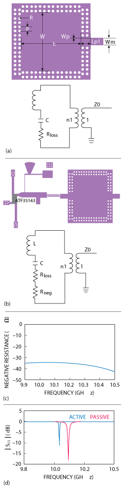
Figure 1 Structure of the passive SIW resonator and its equivalent circuit (a) structure of the proposed active SIW resonator and its equivalent circuit (b) simulated negative resistance Rneg (c) and simulated S11 of active (blue) and passive (red) SIW resonator (d).
An X-Band low phase noise oscillator based on an active substrate integrated waveguide (SIW) resonator uses series feedback to generate a negative resistance, compensating for the resonator’s loss and improving its quality factor (Q). Performance of a negative-resistance oscillator designed using the active resonator is compared with that of a negative-resistance oscillator using a passive SIW resonator. The measured oscillation frequency of the active resonator oscillator is 10.19 GHz with an output power of 8.26 dBm. Its phase noise is -120.1 dBc/Hz at 1 MHz offset, which is about 8 dB lower than that of a similar oscillator with a passive resonator.
Microwave oscillators generally employ series and parallel feedback networks requiring frequency stabilization elements. There are several choices, such as dielectric resonators (DR),1-3 elliptic filters,4 ring resonators5 and hairpin resonators.6 The most important performance parameter is phase noise, since it determines a communication system’s overall performance.7 It is well known that low phase noise oscillators require high Q frequency stabilization elements. Although the DR has a high quality factor, it is not easily integrated with other circuit elements due to its bulky and non-planar profile; while microstrip resonators, though easily integrated, exhibit low Q values.
In recent years, substrate integrated waveguide structures have received much attention. SIW consists of two rows of metallic vias on a substrate and has similar propagation characteristics as that of rectangular waveguide; for example, an SIW cavity’s resonant frequency is determined by its geometric dimensions. Moreover, SIW has several benefits, such as a potentially high-Q factor, low insertion loss and PCB compatibility.
Yet, the Q of an SIW resonator is still limited by dielectric, conductor and radiation losses, which compromise oscillator phase noise performance. This article discusses the use of an active SIW resonator for increased Q in an X-Band low phase noise oscillator.
HIGH-Q ACTIVE SIW RESONATOR DESIGN AND ANALYSIS
There are generally two alternatives for the design of an active resonator: coupling to a negative resistance to compensate for the loss of passive resonator, or equating an active feedback loop to a negative resistance.8 For simplicity, the first one is chosen in this work.
Figure 1a is a top view of a passive SIW reflective resonator and its equivalent circuit (W=L=13.9 mm, R=0.3 mm, P=1 mm, Wp=0.1 mm, Lp1=2 mm, Wm=1.6 mm). The passive SIW resonator is modeled as a series RLC circuit. In this case, Rloss represents the combined dielectric, conductor and radiation losses, and L, C are determined by the SIW’s physical dimensions to obtain the desired resonant frequency.
Because of its similarity with rectangular waveguide,9 the propagation characteristics of the SIW’s TE10 -like mode are very close to a rectangular waveguide’s TE10 mode. Consequently, the resonant frequency of SIW resonator is determined from the following equation:

where W and L are the length and width of the SIW resonator, and c0 and εr are the speed of light in a vacuum and the relative dielectric constant of substrate, respectively. As shown in Figure 1a and the solid line of Figure 1d, the simulated TE101 mode resonant frequency for the passive resonator is 10.09 GHz when W=L=13.9 mm, the unloaded Q is

In order to increase the Q, the denominator Rloss must decrease. From Figure 1d and the method of Drozd and Joines,10 the simulated loaded Q (ZL=50 ohms) of a passive SIW resonator is about 500.
An active device operating in its unstable region can provide an equivalent negative resistance, and a transistor’s unstable region can be enhanced by using series feedback. For a field effect transistor (FET), either a series-feedback inductor or a series-feedback capacitor of a few picofarads may be used.11 In this article, the former is chosen and the series-feedback inductor is realized with two microstrip lines shorted to ground. Figure 1b is a top view of an active SIW reflective resonator and its equivalent circuit. Rneg (Rneg < 0) is the negative resistance. Figure 1c shows the simulated negative resistance Rneg. The equivalent resistance of the active SIW resonator is

Therefore, the unloaded quality factor is

It is apparent that Qactive > Qpassive given the same dimensions and resonant frequency. As shown in Figure 1b and the dotted line of Figure 1d, the simulated TE101 mode resonant frequency for the active SIW resonator is 10.03 GHz , and the simulated loaded quality factor (ZL=50 ohms) is about 2100. The resonant frequency of the active resonator is below that of the passive resonator due to the coupling capacitance, the parasitic capacitance and inductance of the active circuit.
OSCILLATOR DESIGN
In principle, a circuit will oscillate sustainably if the active device continuously supplies energy equal to the energy dissipated. In this case, an active SIW resonator is coupled to a microstrip line in series and then connected to the active device. If the lengths of microstrip line between the source electrode and ground, and the resonator and the active device, are properly chosen, the active device will provide sufficient negative resistance to sustain oscillation at the desired frequency.
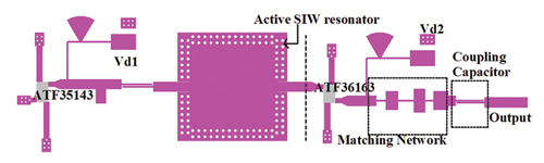
Figure 2 Top view of the overall active resonator oscillator design.
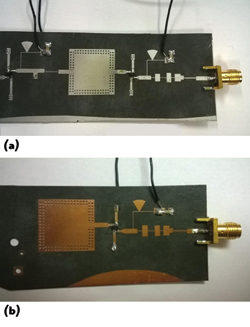
Figure 3 Photograph of active resonator oscillator (a) and passive resonator oscillator (b).
The oscillator is designed based on large-signal measurement.11 Let RIN and XIN represent the real part and imaginary parts of the active device impedance ZIN, and let RL and XL be the real part and imaginary parts of the output matching network impedance ZL. The necessary relation between RIN and RL to initiate oscillation is

In this case, the oscillation is unstable and its amplitude will grow. It will continue to build as long as equation 5 is satisfied; however, the absolute value of the negative resistance, RIN, decreases due to the nonlinear performance of the active device until the oscillation reaches a steady state. When steady-state oscillation is reached, the relationships between RIN and RL, and XIN and XL are:

Oscillator design based on large-signal measurement can provide characteristics of oscillator performance such as power and harmonics. In this situation, the active device impedance ZIN is a function of input power and frequency. According to equations 6 and 7, the output matching network impedance must satisfy the condition ZL = - ZIN.
The matching function requires that both the insertion loss and pass band attenuation ripple of the Chebyshev filter at the fundamental frequency be very small, while the harmonic suppression function requires that insertion loss of the Chebyshev filter at the harmonics be very large. To accomplish both functions, a six- order, short-step Chebyshev impedance transformer is selected.
A short-step Chebyshev impedance transformer12 not only fulfills the output matching requirement at the fundamental, but also enhances harmonic suppression. Because the method and data of Matthaei12 can match only two resistive terminations, however, complex impedance matching is performed using simulation tools per Chen and Peroulis.13
Figure 2 is a top view of the active resonator oscillator. It includes an active SIW resonator, a transistor with output matching network, and an output coupling capacitor to prevent DC current flowing into the measuring instrument.
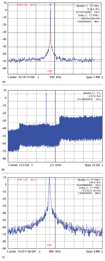
Figure 4 Phase noise of the active resonator oscillator (a) second harmonic suppression of the active resonator oscillator (b) and phase noise of the passive resonator oscillator (c).
MEASUREMENT
Figure 3a shows a negative resistance oscillator with an active SIW resonator fabricated on Rogers RT/Duroid 5880 with a relative dielectric constant εr = 2.2, loss tangent tanδ= 0.0009 and thickness of 0.508 mm. For comparison, a negative resistance oscillator using a passive SIW resonator is also fabricated, as shown in Figure 3b. The two resonators have the same physical dimension except that the active one has two terminations. The active SIW resonator uses Avago’s ATF-35143 pseudomorphic high electron-mobility transistor (PHEMT). Its DC bias voltages are Vgs = 0 V, Vds =2 V. Negative resistance for both the active and passive resonator oscillators is provided by Avago’s ATF-36163 PHEMT. The two ATF-36163 PHEMT’s gates are shorted because of the metallic via walls, and their Vds =2 V.
The output spectrums of the two oscillators are measured with a Rohde & Schwarz FSP spectrum analyzer. Figures 4a and b show the phase noise and second harmonic suppression of the active resonator oscillator. Its oscillation frequency is 10.19 GHz with an output power of 8.26 dBm, and second harmonic suppression is greater than 30 dB. In addition, phase-noise for the active resonator oscillator is -120.1 dBc/Hz at 1 MHz offset, which is almost 8 dB lower than for the passive one. It is apparent from Figure 4a, however, that phase noise of the active resonator fails to decrease further beyond 1 MHz offset. There are two causes, one is noise floor deterioration due to the active device’s noise figure, and the other is due to influences from external noise sources. The former may be alleviated through careful design of the active SIW resonator, and a metal shielded cavity will reduce the effects of the latter.
CONCLUSION
An active SIW resonator is designed to have a Q higher than that of a passive SIW resonator. The phase noise of an X-Band oscillator using the active resonator is -120.1 dBc/Hz at 1 MHz offset, which is about 8 dB lower than that of a similar oscillator with a passive resonator. The results indicate that the use of an active resonator is beneficial in reducing oscillator phase-noise.
ACKNOWLEDGMENT
This work is supported by National Natural Science Foundation of China (Grant No.61201004) and the Fundamental Research Funds for the Central Universities (ZYGX2011J011).
References
- N.M. Mahyuddin, M.F. Ain, S.I.S. Hassan and M. Singh, “A 10 GHz PHEMT Dielectric Resonator Oscillator,” International RF and Microwave Conference Proceedings, September 2006, pp. 26-30.
- A.M. Pavio and M.A. Smith, “A 20-40 GHz Push-Push Dielectric Resonator Oscillator,” IEEE Transactions on Microwave Theory and Techniques, Vol. 33, No. 12, December 1985, pp. 1346-1349.
- B.I. Son, H.C. Jeong and K.W. Yeom, “Design of a Low Phase Noise Voltage Tuned DRO based on Improved Dielectric Resonator Coupling Structure,” Asia Pacific Microwave Conference Proceedings, December 2012, pp. 1121-1123.
- C.H. Tseng and C.L. Chang, “Design of Low Phase-Noise Microwave Oscillator and Wide Band VCO Based on Microstrip Combline Bandpass Filters,” IEEE Transactions on Microwave Theory and Techniques, Vol. 60, No. 10, October 2012, pp. 3151-3160.
- L.H. Hsieh and K. Chang, “Slow-Wave Bandpass Filters Using Ring or Stepped-Impedance Hairpin Resonators,” IEEE Transactions on Microwave Theory and Techniques, Vol. 50, No. 7, July 2002, pp. 1795-1800.
- L. Dussopt, D. Guillois and G.M. Rebeiz, “A Low Phase Noise Silicon 9 GHz VCO and an 18 GHz Push-Push Oscillator,” IEEE Microwave Theory and Techniques International Symposium Digest, Vol. 2, June 2002, pp. 695-698.
- Y.T. Lee, J. Lee and S. Nam, “New Planar High Q Active Resonator and Its Application to Low Phase Noise Oscillators,” IEEE Microwave Theory and Techniques International Symposium Digest, Vol. 3, June 2004, pp. 2007-2010.
- Z. Chen, W. Hong and J.X. Chen, “High-Q Planar Active Resonator Based on Substrate Integrated Waveguide Technique,” Electronics Letters, Vol. 48, No. 10, May 2012, pp. 575-577.
- F.F. He, K. Wu, W. Hong, L. Han and Xiaoping Chen, “A Low Phase-Noise VCO Using an Electronically Tunable Substrate Integrated Waveguide Resonator,” IEEE Transactions on Microwave Theory and Techniques, Vol. 58, No. 12, December 2010, pp. 3452-3458.
- J.M. Drozd and W.T. Joines, “Determining Q Using S Parameter Data,” IEEE Transactions on Microwave Theory and Techniques, Vol. 44, No. 11, November 1996, pp. 2123-2127.
- Guillermo Gonzalez, Foundations of Oscillator Circuit Design, Artech House, 2007, pp. 251-343.
- George L. Matthaei, “Short-Step Chebyshev Impedance Transformers,” IEEE Transactions on Microwave Theory and Techniques, Vol. 14, No. 8, August, 1966, pp. 372-383.
- K. Chen and D. Peroulis, “Design of Highly Efficient Broadband Class-E Power Amplifier Using Synthesized Low-Pass Matching Networks,” IEEE Transactions on Microwave Theory and Techniques, Vol. 59, No. 12, December, 2011, pp. 3162-3173.