
As mobile operators face increasing base station density as well as growing bandwidth requirements, mobile backhaul has become the new challenge. This article defines the architecture for future mobile backhaul networks as proposed in the framework of the FP7 EU SARABAND project. The solution exploits a new and wider frequency band, Q-Band (40.5 to 43.5 GHz), to provide massive capacity. Since full deployment of Q-Band backhaul networks requires new technology development, an overview of disruptive antenna and front end technology developed within this project is also provided.

Figure 1 Network node architecture.

Figure 2 Fabry-Perot cavity.
Demand for bandwidth is growing exponentially as consumers use their mobile devices in more bandwidth-intensive applications. The evolution to 3G and 4G/LTE mobile technologies provides a path to more efficient use of the radiospectrum and progressively higher uplink and downlink speeds to each user. Operators’ forecasts show that additional steps are required to provide sufficient bandwidth.
As a result, operators have begun to introduce small cells into their networks, since this solution has recently emerged as a more cost-effective way for network mobile operators to improve the coverage and capacity of their mobile services. But there are some challenges to leveraging the benefits of small cells. One of the most significantis providing scalable, flexible mobile backhaul to connect small cells back into the network without breaking the small cell business case.
Operators typically use different backhaul technologies for their radio access networks. Nevertheless, existing alternatives such as fiber, digital subscriber line (DSL) and microwave backhaul do not provide the required CAPEX, OPEX and/or performance; therefore, an adequate backhaul upgrade in capacity and cost-efficiency is required. Millimeter wave technology, especially in Q-Band (40.5 to 43.5 GHz), offers a wide frequency spectrum, compactness and lightness of equipment and ease of implementing interference-free system configurations.This makes it very promising for high data rate backhaul applications.
The SARABAND project integrates Q-Band millimeter wave technology for point to multipoint (PMP) transmission to provide a cost-effective solution capable of supplying 150 to 200 Mbps per cell site.
WIRELESS BACKHAUL ARCHITECTURE
The wireless backhaul architecture proposed in SARABAND is a hierarchical, PMP Ethernet-based network composed of nodes linked by radio transmissions and remotely managed by a backhaul network management system (NMS). The solution is a distribution tree connecting a service provider’s point of presence (PoP) to relay nodes ultimately reaching subscriber terminals, grouped terminals and mobile base stations. The main features are:
- A highly flexible PMP network topology that rapidly adapts to an operator’s coverage and capacity requirements while simplifying radio deployment.
- The use of Q-Band, providing a large spectral bandwidth suitable for wide channels (40.5 to 43.5 GHz in 1 GHz sub-bands).
- A radio backhaul network composed of a multiplex of channels that aggregates several 100 Mbps half-duplex (TDD) channels to provide the required throughput (up to 2 Gbps half-duplex per 1 GHz radio transmission).
- Layer 1 and 2 of the network based on the 802.11n and then the 802.11ac standards and aggregation on 802.3ad.
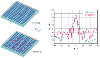
Figure 3 FP antenna gain in the E-plane.
The backhaul network architecture is composed of different types of nodes (see Figure 1). The Transmission Hub (TH) carries traffic in the core network and connects several terminals or relay nodes (RN). Relay Nodes extend system range and avoid the limitations of line of sight. Network Terminal Equipment (NTE) delivers basic services to customers’ points of presence.
To enable any configuration of hierarchical PMP links while meeting the required performance on each segment of the network, the SARABAND project is developing new Q-Band backhaul network technology to increase network node throughput, range and coverage, while reducing cost. Specific developments include:
- Q-Band low-profile, high-gain antennas that will enhance throughput between the TH and the remote sites. Two approaches have been analyzed: Fabry-Perot antennas and lens antennas for medium-gain (20 dBi) and high-gain (>30 dBi) applications, respectively.
- Q-Band programmable multi-beam antennas, which will enhance coverage, reduce interference and save energy. Circular Switched Parasitic Array (CSPA) antennas, for an agile antenna solution, have been analyzed.
- Q-Band miniaturized radio modules based on new substrate, packaging and interconnection processes with the objective of providing modules with low loss, high power and high reliability at a fraction of the price of any currently available radio.
FABRY-PEROT ANTENNA
A Fabry-Perot (FP) antenna is a planar structure providing highly directive beams with properties such as a low profile, lightweight, simple feed mechanism and low cost. This makes it a good candidate to address Q-Band medium gain coverage requirements.
The FP antenna (see Figure 2) is a type of leaky wave antenna, consisting of a partially reflective surface (PRS) at a proper distance from a totally reflective surface (TRS). The resulting cavity may be filled with air or a dielectric material and is excited by a source that is placed inside the cavity.1With an appropriate design, parallel plate modes are excited in the cavity by the source. The power carried by the modes leaks through the PRS, forming a broadside pencil beam in the far field. The distance between the two reflecting surfaces (h) of the cavity and the source position are important antenna parameters.
Considering that the source is positioned at the same level as the PRS, the power radiated in the boresight direction is at a maximum when the following condition is satisfied:
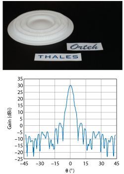
Figure 4 Simulated gain of a low-profile high-gain lens in the H-plane at 42 GHz.

where ΦRis the reflection phase of the PRS, ΨRis the reflection phase of the TRS, h is the Fabry-Perot cavity height, and n = 0,1,2,3,...
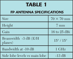
For the SARABAND project, the FP antenna specifications are shown in Table 1. It uses an air-filled FP cavity to reduce losses and provide the best compromise for maximum directivity and pattern bandwidth. The PRS is made of periodic patches (2.88 × 2.88 mm with a 4.2 mm square periodicity) printed on a 0.51 mm thick dielectric substrate placed 2.79 mm above the TRS. A patch within the air-filled cavity is the source of excitation.
An FP antenna produces a highly directive beam with a single feed source, where

for an aperture with an area A. While it is possible to reach up to 90 percent of the theoretical maximal directivity with a few lambda size aperture and a highly reflecting PRS, practical realizations achieve directivities around 50 percent of this limit.
FP antennas, however, are narrowband. Jackson et al.,1 have shown that for a simplified configuration, the product of directivity and 3 dB bandwidth is a constant that can be estimated by the formula:

with n being the cavity refraction index.
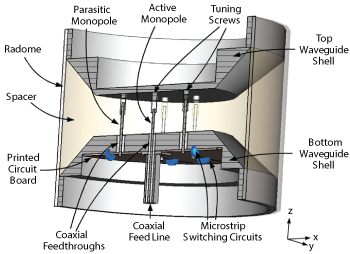
Figure 5 C-Band CSPA antenna 3D model.
The high-gain antenna for the SARABAND project requires a 7.2 percent fractional bandwidth. Basic FP antennas have a fixed directivity-bandwidth product insufficient to meet this requirement; however, the gain can be increased through several complementary means. One is to extend the size of the radiating aperture making the surface through which the leaky wave radiates electrically large, achieving medium to high gain. Typically the PRS can be extended to a size of about 10 × 10 λ. A larger PRS size may not lead to a further gain increase since energy usually leaks from the cavity area being close to the source.
Antenna gain can be further increased by using multiple sources inside the cavity, making more efficient use of the large radiating surface. Furthermore, due to the presence of the PRS, the sources can be spaced 1.5 λ apart without generating grating lobes in the radiation pattern. This excitation mechanism requires a small feed network to distribute the energy between the multiple sources. Figure 3 shows FP antennas with 1 and 16 sources, which have been designed to provide maximum gain. In both cases, the antenna size is 60 × 60 mm (~8.3 × 8.3 λ at 41.5 GHz). Maximum gain is achieved at 41.5 GHz with 1 source (19.2 dBi) and 41.75 GHz with 16 sources (23.3 dBi).
LENS ANTENNAS
In lens antennas, a quasi-point source (the feed) generates a spherical wave which is collected and collimated by a dielectric lens. This results in a plane wave at the antenna output that may provide diffraction-limited gain. Current lens antenna technology is either bulky (refractive design) or low-profile but less efficient (e.g., Fresnel lens).2 To achieve a lower profile, yet efficient design, an innovative lens based on “quasi-optical” RF components is being investigated. It is the transposition of an optical approach, in terms of wavefront control and component design, to the RF domain. This enables the synthesis of an efficient, flat, high numerical aperture lens for controlling and reshaping the wavefront emitted by the Q-Band antenna feed.
Lens antenna operation is based on diffraction and constructive interference between zones composing the lens. The use of sub-wavelength structures and a hybrid lens design overcomes the usual Fresnel-lens limitations and does not suffer from loss of efficiency and bandwidth reduction when implemented in a low-profile configuration.
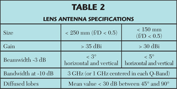
For the SARABAND project, this approach is applied to two different antennas of different sizes in order to cover both TH and NTE requirements. Specifications for the high-gain lens antennas are shown in Table 2. The distance between feed and lens must be optimized to take into account the feed radiation pattern, the lens size and the local sub-wavelength structure. For a given antenna volume, we can compute the configuration giving the highest antenna efficiency and therefore the highest gain. An example is shown in Figure 4.
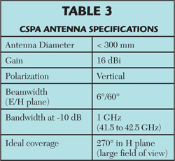
CSPA ANTENNA
An attractive concept for electronic beam steering is the circular switched parasitic array (CSPA) antenna, which is proposed for the agile Q-Band antenna with a large field of view to be used in the repeaters. The basis of this concept for electronic beam scanning is a well-known principle for the controlled forming of radiation patterns of an active antenna element using parasitically coupled passive antenna elements.3 It allows for controlling the radiation pattern in the horizontal (azimuth) plane and steering the beam over a wide field of view. Simple electronic components such as PIN or varactor diodes may be used to tune the parasitic array elements and control beam shape and direction.
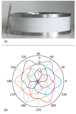
Figure 6 Photograph of the fabricated fixed-beam CSPA Q-Band antenna (a) simulated radiation patterns (b).
A CSPA antenna for a high-power data link application in C-Band (4.4 to 5 GHz) has been previously developed.4 This design uses wire monopole antennas as active and parasitic radiators, sharing a common metallic ground plane of circular shape with the active element placed at its center. These monopoles must have a height of approximately λ/4 and spacing between the active element and the parasitic elements of approximately λ/4. Figure 5 shows a 3D model of a C-Band CSPA antenna.
For the SARABAND project, the specifications of the Q-Band CSPA antenna are shown in Table 3. AtQ-Band the monopole-based CSPA is not feasible because of the height of the monopoles (only 1.8 mm) and the relative size of the additional circuitry (much larger than the antenna elements). Instead, printed microstrip technology is used, based on the CSPA concept.
A demonstrator fixed-beam antenna (without switching elements) is shown in Figure 6a. In a forthcoming version, the beam will be steered by tuning/de-tuning the reflector elements through PIN diode biasing. Because the central active antenna element cannot achieve high gain by itself, the radiated signal is guided through a circular flared horn. At the center frequency of 42 GHz, a standard horn structure would have a length of approximately 300 mm. Due to external limitations the size of the horn must be reduced without reducing its gain; therefore, special measures are incorporated in the horn structure to reduce its size and increase the gain to achieve the desired characteristics. The antenna has an impedance bandwidth of 4.87 percent centered at 42 GHz. Simulated radiation patterns in the horizontal plane at 42 GHz are shown in Figure 6b for various scanning directions, corresponding to different configurations of tuned/detuned reflector elements.
RF MODULES
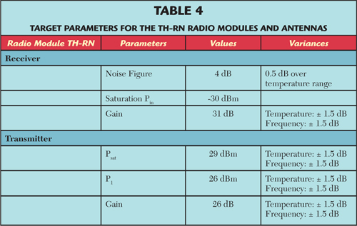
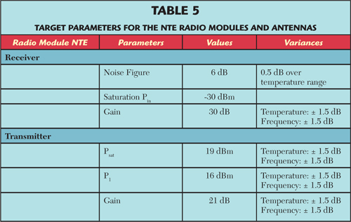
Front end radio modules use advanced GaAs-based monolithic microwave integrated circuit (MMIC) elements and benefit from system-in-a- package (SIP) technology integration to reduce the printed circuit board (PCB) footprint. Specific MMIC chip-sets for the up and downconverters have been developed by the project. These integrate several different functions and provide gain improvements, achieving the 18 dBm power target for the upconverter and 31/33 dB gain for the downconverter with 2.5 dB noise factor. These two chip-sets, together with a power amplifier, are the core elements of the front end radio modules for the network nodes. Tables 4 and 5 list target parameters for the NTE and TH-RN radio modules and antennas.
Specific SIPs using a supporting PCB etched on an organic substrate and including the MMIC chip-sets, filters, isolator/circulator and the antenna interconnection have been designed and manufactured for the SARABAND demonstrator. An example of a manufactured SIP design is the NTE transceiver shown in Figure 7, which consists of a 42 × 25 mm rectangular module. It is composed of the upconverter and downconverter chip-sets soldered on a metallic plate, and a circulator which isolates the uplink from the downlink and allows alternative transmission and reception. A specific connector adapted for 40 to 45 GHz is used for the antenna interface. Signals coming from the local oscillator and the intermediate frequency amplifier and power are supplied through the PCB. Finally, a cover plate shields the module.
One of the biggest challenges has been to successfully miniaturize the front end radio modules. The use of SIP integration and GaAs-based MMIC modules has made this possible. In addition, miniaturization has reduced circuit losses, reduced cost (low site rental, easy installation) and enhanced acceptability. In the future, novel technologies such as Si-Ge-based devices and high frequency switch components could easily be incorporated to improve the performance of the chipsets and the SIP.
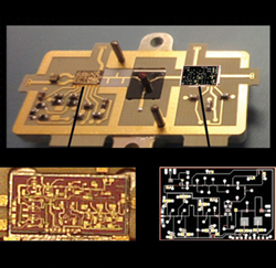
Figure 7 NTE transceiver.
CONCLUSION
The Q-Band PMP backhaul architecture developed through the SARABAND project provides multi-gigabit capacity in a cost-effective manner by exploiting PMP transmissions and the Q-Band spectrum. In addition, the project has several on-going antenna and radio module developments. In particular, a 23 dBi gain Fabry-Perot antenna using multiple sources for medium-gain applications has been designed. Moreover, sub-wavelength structured lens antennas with gains higher than 30 dBi to cover both TH and NTE requirements have been manufactured. For electronic beam steering, a CSPA antenna has been proposed. The designed antenna has a relative impedance bandwidth of 4.87 percent, centered at 42 GHz, and a gain of 16 dBi with a beamwidth of 6°/60° (E/H plane) to cover a horizontal angular range of 270°. Finally, miniaturized front end modules with SIP integration have been designed and manufactured.
References
- D. Jackson, P. Burghignoli, G. Lovat, F. Capolino, J. Chen, D. Wilton and A. Oliner, “The Fundamental Physics of Directive Beaming at Microwave and Optical Frequencies and the Role of Leaky Waves,” Proceedings of the IEEE, Vol. 99, No. 10, October 2011, pp. 1780-1805.
- A. Petosa, N. Gagnon and A. Ittipiboon, “Effects of Fresnel Lens Thickness on Aperture Efficiency,” Proceedings of the 10thInternational Symposium on Antenna Techniques and Applied Electromagnetics, July 2004, pp.175-178.
- R.F. Harrington, “Reactively Controlled Directive Arrays,” IEEE Transactions on Antennas and Propagation, Vol. 26, No. 3, May 1978, pp. 390-395.
- T. Bertuch, “A Circular Switched Parasitic Array Antenna for High Power Data Link Applications,” Proceedings of the3rdEuropean Conference on Antennas and Propagation (EuCAP), March 2009, pp. 2483-2487.
Ruth Vilar received her M.Sc. and Ph.D. degrees in Telecommunications from the Universitat Politècnica de València, Valencia, Spain, in 2007 and 2010, respectively. She joined the Nanophotonics Technology Center as a researcher in 2004. Her research activities are focused on backhaul and access networks, advanced optical techniques for microwave signals and ultra-high speed data transmission. Other research interests include optical performance monitoring and packet-switched networks.
Javier Martí received his Ingeniero de Telecomunicación degree from the Universidad Politécnica de Catalunya, Spain in 1991, and his Ph.D. degree from the Universidad Politécnica de Valencia, Spain in 1994. In 1989 and 1990, he was an assistant lecturer at the Universidad Politécnica de Catalunya. From 1991 to 2000, he held the positions of lecturer and associate professor at the Telecommunication Engineering Faculty. Martí is currently the director of a national research centre for photonic technologies at the Valencia Nanophotonics Technology Centre (NTC), in Valencia, Spain. He has authored 7 patents and over 185 papers in refereed international technical journals in the fields of broadband hybrid fiber-radio systems and microwave/millimeter wave photonics, access networks, terabit/s OTDM/WDM optical networks, advanced optical processing techniques for microwave signals and ultra-high speed data transmission and silicon photonics.
Romain Czarny received his Engineering degree from ENST Paris (Ecole Nationale Supérieure des Telecommunications, now Télécom ParisTech) in 2002. He joined Thales Research & Technology (TRT) in 2006 where he received a Ph.D. in collaboration with IEMN working on optically driven sub-millimeters sources. After three years as project manager in a Thales subsidiary, Czarny joined the TRT LCDT Laboratory (Component, Technologies Integration & Demonstration Lab) with activities dedicated to optical concepts applied to RF technologies such as millimeter wave imaging and lens antenna technologies.
Maciej Sypek received his M.Sc., Ph.D. and habilitation degrees from the Warsaw University of Technology in 1987, 1992 and 2009, respectively. He is now the CEO of the Polish innovative company Orteh, active in the areas of information technologies and optics. He deals with optical design and numerical simulations of propagation electromagnetic radiation in demanding configurations from the extreme ultra-violet to the terahertz range. Sypek is an expert in the design and characterization of sub-wavelength elements. He is an author and co-author of more than 50 articles published in pre-reviewed scientific journals.
Michal Makowski received his M.Sc. and Ph.D. degrees from the Warsaw University of Technology in 2001 and 2007, respectively. His activities in Orteh are focused on the fabrication and characterization of sophisticated, optical, diffractive and holographic elements for the wide range of frequencies. Makowski is an author and co-author of more than 40 articles published in pre-reviewed scientific journals.
Cédric Martel joined the antenna department of ERA Technology (UK) in 1997. In 2002, he received his Ph.D. degree following a part-time research program in collaboration with ERA Technology and the University of Surrey. Since January 2006, he has been working as an antenna research engineer in the department of electromagnetism and radar (DEMR) of ONERA in France. Martel’s research interests include leaky wave antennas, reconfigurable antennas, phased arrays, metamaterials and their antenna applications.
Thomas Crépin received his M.S. degree in physics from University of Lille, France, in 2002 and his Ph.D. degree from the University of Lille, France, in 2006. From 2002 to 2006, he was with Institut d’Electronique, de Microélectronique et de Nanotechnologie (IEMN), Lille, France, where he worked on terahertz technology and metamaterials. Crépin is currently working in the field of antenna and metamaterial design at ONERA, The French Aerospace Lab, in the Electromagnetism and Radar Department, Toulouse, France.
Fabrice Boust received the Agrégation of Physics in 1981 from the École Normale Supérieure de l’Enseignement Technique. He earned a Doctorate of Science in 1989 from the Paris Sud University. Boust is currently a senior expert in the Radar Department of ONERA (the French Aerospace Lab) and in SONDRA (a joint laboratory established between Supelec, ONERA, the National University of Singapore and DSO National Laboratories). His research interests are dynamics of magnetic particles, radar absorbing materials and metamaterials for antennas.
Ronald Joseph received his Ph.D. degree from Kumamoto University, Japan in 2011. He was a Lecturer in Electronics at Christ Junior College, Bangalore, India from 2002 to 2008. Joseph is currently working at the Fraunhofer Institute for High Frequency Physics and Radar Technique, FHR, Wachtberg, Germany. His research interests are antenna design and electromagnetic modeling.
Kai Herbertz received his Ph.D. in electrical and electronic engineering from Imperial College London, U.K., in 2010. Since 2011, Herbertz has been working as a researcher for the Fraunhofer Institute for High Frequency Physics and Radar Techniques (Fraunhofer FHR). His research interests include metamaterials and electromagnetic modeling.
Thomas Bertuch received his Ph.D. from RWTH Aachen University, Aachen, Germany, in 2003. His doctoral research was developed at the Research Institute for High Frequency Physics and Radar Techniques of the Research Establishment for Applied Natural Science e.V. (FGAN-FHR), Wachtberg, Germany. In 2004, he was a senior antenna scientist with the Defence, Security and Safety Institute of The Netherlands Organization for Applied Scientific Research (TNO), The Hague, The Netherlands. Since 2005, Bertuch has been with the FGAN-FHR which, since 2009, is the Fraunhofer Institute for High Frequency Physics and Radar Techniques (Fraunhofer FHR); where he is currently Team Leader of Antennas and Front End Technology. From 2000 to 2009, he was Lecturer of RF engineering at the Bonn-Rhine-Sieg University of Applied Sciences, Sankt Augustin, Germany. Since 2012 he has been Lecturer of Antennas and Wave Propagation at the Aachen University of Applied Sciences, Aachen, Germany. Bertuch’s research activities include antenna and microwave circuit design, engineered electromagnetic materials (metamaterials), radar system design and electromagnetic modeling.
Alain LeFevre graduated from the Conservatoire des Arts et Métiers specializing in Macromolecule Polymers. He joined the Thales microwave department in 2000 to develop microwave component industrial activities and became involved in IFF (Identification Friend or Foe) microwave and X-Band activities. He has been in charge of studying a Q-Band Solid State Power Amplifier in the Thales microwave department.
François Magneis responsible for research and development at Bluwan. He began his career at the French DGA (French department of defence), creating missile guidance and directional radar systems. He later became director of industrial relations at French research think tank CNRS, and went on to lead advanced research at TRT-Philips and Thomson CSF. When the Thales Group acquired Thomson CSF, he became the chief scientist for the Thales CNI (communication, navigation and identification) division. Magne was a critical contributor in the development of advanced communications systems, as well as the development of satellite and high speed broadband technologies. In 2002, he became the vice president of technology in charge of innovation and industrialization at Thales, with whom he co-founded Bluwan in 2005.