
A compact bandwidth-broadened and isolation-improved MIMO antenna appropriate for LTE communication employs a small 0.034λg long radiator designed to have an in-phase and dense electric field flux at the zeroth order resonance (ZOR) of 2.5 GHz for circumventing the problem of degraded antenna gain and four thin FR4 layers to create closely located resonances for expanding the bandwidth. The radiator is used in the design of two antennas on the top-edge of a MIMO handset with a total length equal to 0.108λg (much less than a quarter-wavelength). The two radiating elements are separated by just 10 mm and a folded line between them is optimized to obtain isolation above 10 dB over the 250 MHz bandwidth. The design is validated with a full-wave simulation that is in good agreement with measurements of the fabricated prototype, which uses a low cost FR4 process versus ceramic-based chips or LTCC.
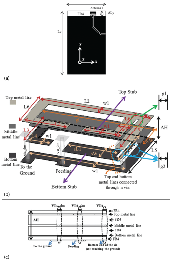
Figure 1 Geometry of the radiating element attached to the ground; top overall view (a), 3D view of the radiating element (b), side-view showing the thin layers (c).
Multi input, multi output (MIMO) antennas must provide higher quality mobile communication through diversity in RF signal transmission and reception. This challenges antenna designers to increase isolation between multiple antennas while reducing antenna size. A number of MIMO antennas were prototyped by Mak et al.,1 with a feature of trapping the undesirable interaction between one element and the other, imitating a closed current loop suppressing a long current flow. The radiation patterns and isolation are acceptable, but the structure is physically large, occupying the top edge and two sides of the handset device. K. Payandehjoo et al.,2 utilized an electromagnetic band gap (EBG) structure to increase diversity gain by weakening the coupling between two antennas; however, the structure is large and the frequency is outside the WiMAX band. Wang, et al.,3 demonstrated two microstrip fed antennas having the layered and vertical parts of the radiators perpendicular to the layered ground by periodically meandering a decoupling element for better isolation. Although isolation is greater than 12 dB, the structure uses a microstrip fed monopole-type decoupling element occupying a large volume. Simple meandered quarter-wave long radiators are separated by a split ground and a hybrid coupler by Sharawi et al.,4 and Bhatti et al.,5 respectively. The radiators are connected in the LC-based branch coupler for lower coupling,5 but 3D folded monopoles share a shorted loop for better decoupling.6 A very compact radiator using a ZOR split ring resonator (SRR) is proposed and adopted for miniature symmetric MIMO antennas by S. Yoo et al.7 It occupies two-thirds of the top edge of a handset device, with a gain larger than 2 dBi and isolation of over 12 dB.
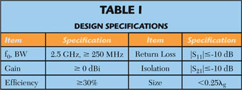
This article describes a compact bandwidth-widened and high-isolation MIMO antenna for LTE mobile communication designed to meet the specifications in Table 1. It utilizes a small 0.034λg radiator, similar to that described by Yoo et al., but with the addition of four thin FR4 layers to generate closely located resonances for broader bandwidth. The radiator design is applied to radiating elements one and two on the top-edge of a handheld MIMO device with the entire length equal to 0.108λg. In contrast to the other antennas designed for a similar frequency band that usually occupy a large proportion of the upper edge area of the ground; this one, in the form of a thin layered structure, has a length less than 1/6.5 Wx (see Figure 1).
ANTENNA ELEMENT DESIGN
The radiating element includes a pair of split ring resonators (SRR) as described by Yoo, but they are on different layers to induce resonance at closely located frequencies near 2.5 GHz for widening the bandwidth, and to align and gather the flux of the electric field in one direction through the layers for achieving a satisfactory antenna gain using the ZOR phenomenon. The platform including the ground in Figure 1a has dimensions Wx=53 mm, Ly=88 mm, and ΔLy=7 mm.
The antenna element attached to the ground and feed points has a volume L2×L5×AH = 8.5 × 6 × 2.3 mm = 117.3 mm3. Confined to this volume, are two resonant current paths. The shorter one (bottom metal line or bottom SRR) corresponds to the higher resonant frequency and the longer one (top metal line or top SRR) corresponds to the lower resonant frequency. As shown in Figure 1b, the main part of the shorter resonance path is the cascade of L1, L5, L2, L3, and L4, while the longer path consists of L1, L5, L2, L6, and L7, with the via connecting the top and bottom metal lines. The other vias, for example Via_dm near the shorting point and Via_dm near the feed, have no electrical function but are there for remanufacturing purposes.
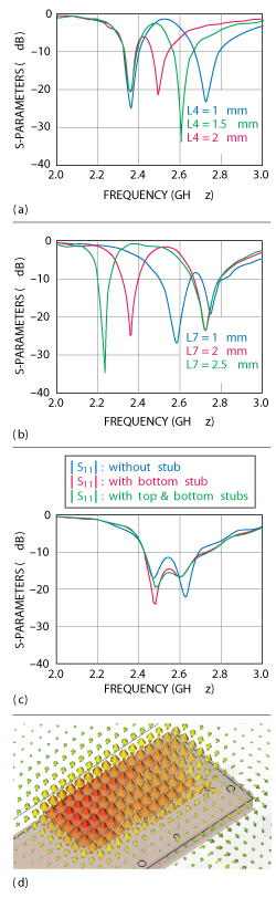
Figure 2 |S11| versus L4 for the high frequency resonance (a), |S11| versus L7 for the low frequency resonance (b), |S11| versus stub length (c), ZOR electric field distribution (d).
Because the top and bottom SRRs are separated by two FR4 layers, as shown in Figure 1c, which might result in a weak interaction, the middle metal line (gL × gW) is inserted to strengthen the coupling. Stubs are included in the top and bottom metal lines to control the coupling as well as the resonance lengths. Parametric studies are used to determine the structure’s physical dimensions for alignment of the two resonant frequencies just above and below 2.5 GHz.
The bottom metal line with L4 varied from 1 through 2 mm controls the high frequency resonance as shown in Figure 2a. The low frequency resonance is changed by the top metal line with L7 ranging from 1 through 2.5 mm as shown in Figure 2b. After several parametric sweeps the dimensions of 13.5, 6, 2.3 mm, 6.9, 8.5, 2, 1, 5.15, 2.8, 1.8, 0.8, 0.2, 0.2, 2.5, and 8.5 mm are chosen for AL, AW, AH, L1, L2, L3, L4, L5, L6, L7, w1, g1, g2, gW, and gL, respectively. All the dielectric materials are FR4 with εr= 4.3 and loss tangent of 0.02.
Due to the strength of the two resonances and the distance between them, there are at this point, two narrow bands instead of one wide band. This is corrected with the addition of the top and bottom stubs and the adjustment of lengths sL1, sL2 and sL3. As the length of the bottom stub (bottom SRR) grows, the high frequency resonance moves downward from 2.63 to 2.6 GHz. Also, as the top stub is trimmed to increase coupling with the bottom metal line, the low frequency resonance becomes slightly weaker and its steep curve becomes smoother. This is observed in Figure 2c as the introduction and adjustment of the stubs moves the split resonant frequencies closer and the bandwidth becomes wider. The dimensions 3.9, 2.9, and 3 mm are chosen for sL1, sL2, and sL3, respectively. As shown in Figure 2c, the bandwidth is marginally greater than 250 MHz. This is further adjusted and finalized in tuning of the the two-element MIMO antenna design.
Besides return loss, the ZOR phenomenon provides another beneficial characteristic. As expected, the in-phase and dense flux of the electric field is generated in the frequency band, as shown in Figure 2d. This is instrumental in producing an antenna gain over 0 dBi in a compact radiating structure as short as 0.034λg.
COMPACT MIMO ANTENNA WITH HIGH ISOLATION
Due to its substantial size reduction, the antenna element design can be expanded to applications requiring multiple antennas (e.g. mobile phones) in a limited space. Figure 3a shows a MIMO antenna with the two compact radiating elements connected through a folded line. In Figure 3b, the folded line serves as a decoupler, inspired by a magnetic wall. Coupling to the antennas is through gaps (g3) so as not to affect their previously determined physical dimensions. The initial value of L7 alone changes from 1.8 to 2 mm. With mL, mW, mG, g3, dW, dL1, dL2, dL3, and dL4 equal to 27, 6, 10, 0.1, 0.3, 5.7, 2.6, 3.95, and 4.55 mm as, respectively, the folded line almost suppresses coupling between the antennas, as shown in Figure 3c. Also, the full-wave simulated S11 and S21 meet the required BW, ƒo and isolation as shown in Figure 3d. Now, the structure is fabricated and its performance is test for validation.
Figure 4a shows that measured S11 and S21 agree well with simulation and are in compliance with design specifications in Table 1. Measured far-field patterns, plotted in Figure 4b, show good agreement with predictions, achieving a gain ≥ 1.5 dBi and efficiency ≥ 40 percent averaged over the bandwidth, suitable for mobile communication.
CONCLUSION
Using a small radiating structure as its basis, a novel compact ZOR MIMO antenna with enhanced bandwidth and high isolation has been designed. Its total length of less than 0.11λg and its performance makes it suitable for mobile LTE communication applications.
ACKNOWLEDGMENT
This work was supported by the Research Grant of Incheon National University with S. Kahng as the lead-author and in collaboration with LG Innotek Co. Ltd.
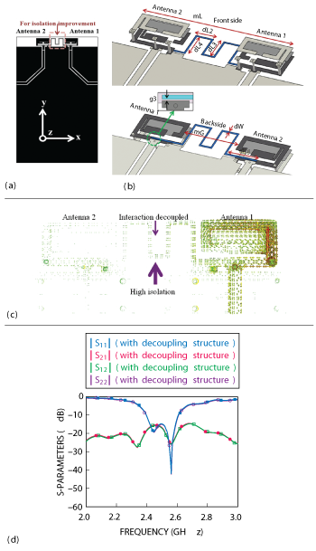
Figure 3 MIMO antenna; top view (a), front and backside expanded view (b), isolation image (c), simulated |S11| and |S21| (d).
References
- A.C.K. Mak, C.R. Rowell and R.D. Murch, “Isolation Enhancement Between Two Closely Packed Antennas,” IEEE Transactions on Antennas & Propagation, Vol. 56, No. 11, November 2008, pp. 3411-3419.
- M.K. Payandehjoo and R. Abhari, “Employing EBG Structures in Multiantenna Systems for Improving Isolation and Diversity Gain,” IEEE, Antennas and Wireless Propagation Letters, Vol. 8, 2009, pp. 1162-1165.
- X. Wang, Z. Feng and K.M. Luk, “Pattern and Polarization Diversity Antenna With High Isolation for Portable Wireless Devices,” IEEE Antennas and Wireless Propagation Letters, Vol. 8, 2009, pp. 209-211.
- M.S. Sharawi, S.S. Iqbal and Y.S. Faouri, “An 800 MHz 2x1 Compact MIMO Antenna System for LTE Handsets,” IEEE Transactions on Antennas & Propagation, Vol. 59, No. 8, August 2011, pp. 3128-3131.
- R.A. Bhatti, S. Yi and S.O. Park, “Compact Antenna Array With Port Decoupling for LTE-Standardized Mobile Phones,” IEEE Antennas and Wireless Propagation Letters, Vol. 8, 2009, pp. 1430-1433.
- M.S. Han and J. Choi, “MIMO Antenna Using a Decoupling Network for Next Generation Mobile Application,” Proceedings of the 9th International Symposium on Communications and Information Technology, September 2009, pp. 568-571.
- S. Yoo, S. Kahng, and J. Kim, “A Compact MIMO Antenna using ZOR Split Ring Resonator Radiators with a Decoupling Structure,” Microwave Journal, Vol. 54, No. 11, November 2011, pp. 26-33.

Figure 4 Measured |S11| and |S21| (a), photo and beam patterns of antennas 1 and 2 (b).
Kyungseok Kahng received his B.E. in 2012 and is currently studying for his M.E. at the Incheon National University, Incheon, Korea. His research fields are microwave engineering, RF components, antennas, radar and metamaterials.
Sungtek Kahng received his Ph.D. in electronics and communication engineering from Hanyang University, Korea in 2000, with a specialty in radio science and engineering. From 2000 to early 2004, he worked for the Electronics and Telecommunication Research Institute on numerical electromagnetic characterization and developed RF passive components for satellites. In March 2004, he joined the Department of Information and Telecommunication Engineering at the University of Incheon where he has continued research on analysis and advanced design methods of microwave components and antennas, including metamaterial technologies, MIMO communication, and wireless power transfer for M2M/cyber-physical systems.
Inkyu Yang received his B.E. in 2012 and is currently studying for his M.E. at the Incheon National University, Incheon, Korea. His research fields are microwave engineering, RF components, antennas, wireless power transfer and metamaterials.
Qun Wu received his B.S. in radio engineering,his M.E. in electromagnetic fields and microwave technology, and his Ph.D. in communication and information systems engineering, all at Harbin Institute of Technology, Harbin, China, in 1977, 1988, and 1999, respectively. Since 1990, he has been a professor with the Department of Electronic and communication Engineering at HIT, China.