
The high value of scarce cellular radio spectrum and demand for ever higher data rates have spurred a great deal of innovation in optimizing mobile radio links, primarily by increasing signal bandwidth and modulation complexity. The consequences for RF transmitter power amplifiers (PA) are increased average output power and higher peak-to-average-power ratios (PAPR), which mean lower PA efficiency and disproportionately high power consumption. For mobile handsets, transmitter efficiency and battery life are not only reduced, but overheating becomes an issue as mobile PA footprints shrink and filter losses mount with new band interoperability and carrier aggregation requirements. Base station transmitters have long had the luxury of a stable antenna environment, complex support electronics, digital processing techniques and envelope tracking (ET).1 ET has become viable for mobile devices and is now appearing in products. Given BlackBerry’s years of internal and collaborative research in mobile radio, this article concentrates on ET for mobile LTE handsets. It also applies to any high PAPR transmitter used with WCDMA, HSPA, DTV and Wi-Fi.
Several means of increasing PA efficiency (ratio of RF power output divided by total supply power is used here) at less than maximum power have been employed in the mobile marketplace with varying degrees of success. Adaptive quiescent current bias has been widely used on PAs since the 1990s, while other PA designs simply bypassed the final stage for low power. A power-saving technique which has become especially popular in the past decade is “average power tracking” (APT). Figure 1 shows the concept of APT, where the PA voltage supply, VPA, is tailored on a frame-by-frame basis to the minimum required to accommodate modulation peaks for maintaining RF performance. This puts the PA slightly into compression to improve efficiency.
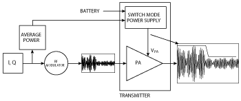
Figure 1 Average power tracking (APT) transmitter.
Since the efficiency of concern to battery longevity is the product of the APT power supply and PA efficiencies, Figure 1 defines the “transmitter” to be optimized as the supply and PA together. Not only must the supply be efficient but VPA must also have minimal noise so that it will not modulate the compressed PA and produce spurious RF products. Fortunately, the past decade has seen the nearly universal adoption of APT given recent improvements in the efficiency (nearly 95 percent), size and cost of low noise switched mode power supplies.
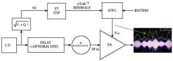
Figure 2 Envelope tracking (ET) transmitter.
Handset transmitters most often operate at power levels significantly below maximum, and the above-mentioned schemes deliver value in reducing the amount of energy consumed at middle power levels. They do not, however, improve transmitter efficiency at high power which would reduce peak battery current and avoid overheating. Envelope tracking, in contrast, is most effective at high power and can also complement APT.
Figure 2 shows the concept of ET. Here, VPA is generated by an ET power supply (ETPS) and applied to the PA’s final stage at a level calculated from the instantaneous RF signal envelope, Ve. This operates the PA efficiently in controlled compression at all significant instantaneous powers. ET is not to be confused with Kahn’s envelope elimination and restoration (EER) technique, since the PA RF input is fully modulated and VPA does not have to track the envelope to very low values. The inset on the right of Figure 2 shows oscilloscope traces of the PA RF output and VPA of an actual ET system.
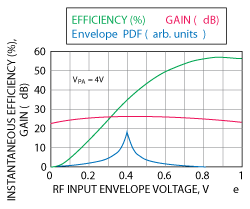
Figure 3 Efficiency characteristics of a linear PA with constant supply voltage.
EFFICIENCY OF APT OPERATION
Figure 3 shows the instantaneous efficiency (instantaneous RF output divided by instantaneous total DC input power) of a commercial two-stage InGaP PA module as a function of RF input envelope voltage. In this example, fixed supply voltages are applied to each stage, with a value of VPA=4 V applied to the final stage. The envelope, Ve, as shown in Figure 2, is defined as the instantaneous RF input amplitude. If the RF input is generated by a modulator with quadrature components I and Q (the case in most mobile transceivers today), the envelope is proportional to the magnitude of the modulation:

As the PA is driven by higher input levels, efficiency improves as the final stage comes to fully utilize the supply voltage available to it. More drive puts the output into compression and output peaks are softly clipped, reducing gain and increasing distortion. In practice, a compromise is reached between efficiency and distortion (e.g., adjacent channel leakage ratio).
The lower trace of Figure 3 plots the probability density function (PDF) of the input RF envelope for an LTE QPSK modulated mobile uplink signal, which can have a PAPR up to 6 dB, so that envelope peaks are twice the average. It can be seen that the greater the signal PAPR, the lower the average signal level at the onset of significant distortion. For the LTE example shown, efficiencies of only about 35 percent are reached in APT mode with InGaP handset PAs. Factoring in a switching supply with 93 percent efficiency, APT transmitter efficiencies in the low 30 percent range can be achieved.
ET OPERATION
Figure 4 shows a family of efficiency curves for different fixed supply voltages from the same PA data used for Figure 3. The heavy black line connects points of maximum efficiency on the curves for each Ve. This defines a relationship called the ET look-up table (ET LUT) between Ve and the supply voltage, VPA, which will maximize instantaneous efficiency at each point of the signal. The ET LUT, plotted below the efficiency curves of Figure 4, is applied by the ET DSP block in Figure 2. In practice, VPA must maintain a minimum value for proper operation (0.6 V in this example) but there is little energy to save at very low values of Ve. The signal now spends most of the time at an efficiency approaching 50 percent, hence a significant increase in transmitter efficiency can be expected, assuming high ETPS efficiency.
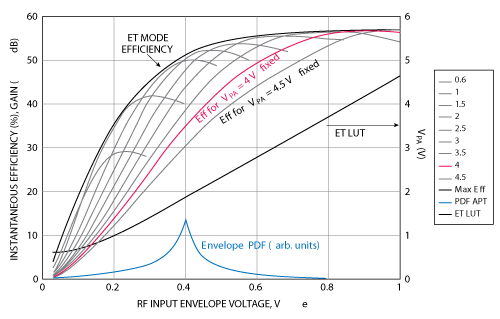
Figure 4 Efficiency characteristics of a linear PA with envelope tracking.
A few practical considerations of ET can now be summarized:
- VPA should be synchronized to the RF envelope by a small fraction of the symbol period, typically to 1 percent of the inverse signal bandwidth (e.g., one nanosecond for 50RB LTE signals) for mobile transmitters.
- The ETPS does not go all the way down to zero but has a defined minimum.
- VPA is not necessarily a linearly scaled version of Ve, but in practice can be expected to be a monotonic function of it. This is a valuable consideration for the ETPS as this avoids cusping of VPA at envelope minima and so minimizes its output bandwidth in operation.
- ET offers more potential improvement in efficiency as signal PAPR increases.
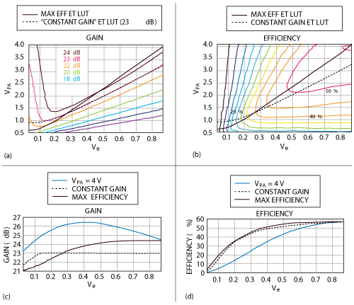
Figure 5 Gain and efficiency characteristics of different ET LUTs.
At first glance the concept of ET may appear technically daunting since the envelope tracking power supply (ETPS) of Figure 4 must be efficient, very fast, and yet produce very low output noise. Also, PA characteristics are complex enough without considering interactions with a dynamic power supply, so one might conclude that gross distortion would result. It will be shown, however, that ET can improve PA characteristics as well as save power.
Figure 5 displays characteristics of our mobile PA as contours of efficiencies and gain against VPA and Ve. The ET LUT derived in Figure 4 which maximizes efficiency is readily traced on the contours of efficiency, as shown by the solid black line in (see Figure 5b). Overlaying this maximum-efficiency ET LUT on contours of gain (see Figure 5a), however, shows gain variation over the signal’s excursion (shown in Figure 5c), which is monotonic and no more than gain variation of APT with VPA = 4 V.
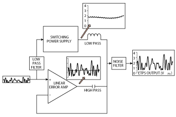
Figure 6 ET power supply block diagram.
Alternatively, consider the “constant gain” ET LUT shown by the broken black line in (see Figure 5b), which follows a constant gain contour (23 dB in this case) except for low Ve, where it is kept at minimum VPA for monotonicity. It offers flat gain at significant power and hence, high linearity, amounting to a form of amplitude predistortion. Remarkably, this ET LUT achieves nearly the same efficiency as the efficiency-optimized case, as shown in Figure 5d. Since this does away with the need for input signal predistortion, at least for amplitude, the use of constant-gain ET LUTs is popular. Such linearization also allows the PA to be driven harder so that the envelope PDF peak can be increased to yield even higher efficiency. As a result, mobile PA module efficiencies approaching 60 percent have been achieved with InGaP PAs in ET operation.
The PA’s phase response is also a source of distortion, but ET mode mobile PAs on the market have benign phase characteristics comparable to PAs optimized for APT operation. Phase-only predistortion with constant gain ET LUT is an option.
THE ET POWER SUPPLY (ETPS)
Higher PA efficiency will not translate to ET transmitter efficiency unless the ETPS is also efficient. High speed switching supplies are available which can effectively apply a mild form of ET for minimal extra cost, but these are not accurate or quiet enough for full tracking.
Figure 6 shows a simplified popular architecture which has been conceptually adopted with variants by many commercial ETPS manufacturers. It is essentially an APT supply coupled with a high speed, low noise linear error amplifier. On mobile handsets, changing from APT to ET operation results in small incremental size (less than 10 mm2) and cost. In the implementation of Figure 6, the APT and error amplifier outputs are combined with a simple diplexing circuit which presents a low pass response to the APT output and a high pass path to the error amplifier.
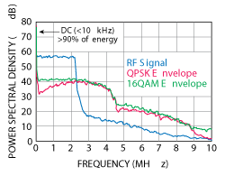
Figure 7 Power spectra of LTE signals and envelopes.
While the error amplifier is quite inefficient, it does not have to supply much energy. Figure 7 shows the power spectrum of an LTE 5 MHz uplink signal against the corresponding ETPS output (VPA) power spectra for QPSK and 16QAM modulation. More than 90 percent of the energy is contained at frequencies below 10 kHz, which corresponds to shifts in power from frame-to-frame in LTE, and is well within the APT switching supply’s capability. Only about 5 to 8 percent of the energy lies above 10 kHz for QPSK and 16 QAM modulations, respectively. At high power, commercial ETPS efficiencies of over 90 percent are common for WCDMA uplink signals, and 85 percent can be achieved even for 20 MHz LTE 16QAM. Higher bandwidths and efficiencies will soon emerge in the market. Regarding the ETPS frequency response for mobile LTE and WCDMA transmitters, industry experience and simulations3 show that the ETPS output can be band limited to between 50 and 100 percent more than the nominal signal bandwidth while maintaining acceptably low levels of PA output distortion for mobile applications. Another special feature of the AC coupled design of Figure 6 is the ability of the ETPS output to momentarily exceed the battery voltage, which means that PA operation can be extended to higher voltages (with appropriate change of PA loading) even at end of battery life.
With ET efficiencies of over 50 percent and ETPS efficiencies of 90 percent, mobile ET transmitter efficiencies of 45 percent for LTE signals are being achieved at high power. Compared to a typical high power APT transmitter efficiency of 32 percent, ET promises less than 75 percent of the transmitter power consumption and less than 60 percent of the heat generation of APT mode at high power.
For less than maximum power, achievable ET efficiency and ETPS overhead power consumption erode ET’s advantage. With mobile LTE transmitters, the ETPS linear amplifier is turned off and APT mode is resumed for medium output powers (typically 8 dB below maximum).
DESIGN OF ET POWER AMPLIFIERS
Power amplifiers designed for ET operation entail some minor modifications. Since the supply is modulated to frequencies somewhat higher than the signal bandwidth, bias bypass capacitors on modulated stages must be eliminated or minimized. A short supply trace from the ETPS to the PA in a handset can have an inductance of a few nH, so an accurate supply drive to 30 MHz for a 20 MHz LTE signal sets an upper limit of about one nF total shunt capacitance for all PAs driven. A hazard of minimizing local PA bypass capacitance is RF parametric stability, especially at low frequencies, but major mobile PA manufacturers are now producing suitable devices.
Since the PA may be loaded for higher voltage operation, transistor breakdown voltage should be increased. Higher voltage and compressed operation also reduce power gain, so gain may have to be increased a few dB to achieve required output power with existing transceiver RF output power capability. This makes attention to stability even more critical.
PA gain should not be too sensitive to VPA. This allows a healthy excursion of VPA with minimal gain variation so that ET mode efficiency can be maximized. Excessive gain expansion against input power should also be avoided. The RF phase response along the expected ET supply response should also be minimized and monotonic if possible.
Cautious application of ET will see VPA applied only to the final stage of the PA, with previous stages operated from fixed voltages, since modulating multiple stages simultaneously makes ensuring stability and well behaved dynamic characteristics even more difficult. Nevertheless, handset PAs with ET applied to two stages simultaneously have emerged in the market as PA manufacturers gain design experience, allowing somewhat higher transmitter efficiency.
CHALLENGES
An ET system introduces some new but tractable design challenges:
Noise Conversion: Since PA gain is a function of supply voltage, supply (VPA) noise can modulate the RF output and manifest as spurious RF noise outside of the desired signal. Such noise conversion is quite large with ET PAs as they operate in efficient compression over most of the envelope. In frequency duplexed systems like WCDMA and LTE-FDD, this can become a critical problem if supply noise at frequencies close to the duplex spacing converts into the receive band as interference. With ET, unlike APT, the supply contains spectral energy exceeding the RF signal bandwidth, which can come close to the duplex frequency of some bands (e.g. Bands 2 or 17), making adequate voltage supply filtering critical. While this has proven to be a significant problem in handset ET transmitters, it is successfully mitigated with painstaking attention to ETPS design, filtering, and component layout.
Load Impedance Changes: PA gain is also a strong function of its load impedance. Changing impedance at the PA final transistor necessitates changing the scale of both the RF input drive and VPA, and by different factors, to maintain optimum ET performance. Even apart from large mobile antenna impedance shifts, the PA faces duplex filters which have significant impedance variation over frequency and temperature. This can make for tedious characterization and calibration. This problem is common to APT transmitters, however, and ET transmitters appear to suffer no more - if not less - distortion over uncompensated mismatch than APT.2 Active antenna tuning is also starting to appear as a handset feature, along with antenna line impedance estimation, to stabilize antenna impedance and compensate its effects.
Memory Effects: PA characteristics are typically modeled quasi-statically for ET operation, so that the output is an instantaneous function of VPA and RF input power. As the speed of modulation increases, intrinsic PA memory effects such as junction charge storage and bias network response can become significant. The ETPS can suffer slew rate limitations and rising VPA supply line impedance. Resultant distortions can become apparent in mobile handsets for RF modulation bandwidths of 20 MHz. Higher bandwidth applications in the future will require careful attention to memory effects.
Filter Group Delay: In addition to significant impedance changes in the pass band, high order duplex filters on the transmitter output (and in some cases, input) are characterized by large and variable group delays which can approach a symbol period across the RF signal bandwidth. While OFDM signals used for LTE and Wi-Fi are resistant to this, the signal envelopes are not. An investigation by the author suggests that output duplexers can add doubly delayed and distorted reflections from the duplexer’s antenna side to combine with and distort the envelope at the PA output, causing suboptimal tracking. This constitutes a sort of memory effect, and this can be minimized by good PA transmission line matching.
THE ROLE OF MIPI®
The ETPS must supply the PA with high fidelity, accurate timing and low noise, so its control is as critical. This begs design guidelines and specification of the interface between the ETPS and the controlling transceiver or processor. In the middle of 2011, manufacturers of RF transceivers, modem processors and OEMs chartered the Analog Control Interface Working Group (ACI WG) within the MIPI Alliance to develop control interface specifications which impact analog chip-to-chip connections. Within that WG, an envelope tracking sub-group was formed to specifically address the interface between the transmitter and envelope tracking power supply. They defined a differential analog voltage ETPS control interface dubbed “eTrakSM”, which is shown in Figure 2. The first version of the specification was released in October 2013.4 Further versions are being drafted.
The eTrak specification prescribes control signal amplitude, accuracy, frequency response, drive capability and spectral noise limits. The ACI WG has also developed an extensive application note3 which discusses many design challenge topics researched by group members, as well as technical recommendations, such as slew rate and ETPS common mode rejection. A suite of bench verification tests5 is currently being drafted.
ET IN THE FUTURE
While signal bandwidths of up to 20 MHz are presently targeted for mobile products with ET, higher signal bandwidths and PAPR demanded by LTE-Advanced carrier aggregation (PAPR of 9 dB or more) and 802.11 will require better error amplifier high frequency performance. PA memory effects will have to be reduced and unless band allocations and duplex spacings are increased, dispersive effects of filter components will become more severe. Higher integration of ET components will be necessary to minimize PA supply line issues. Efforts are underway to integrate ETPS with CMOS PAs for better ET supply coupling and integration with front end components, as well as compensation of historically lower CMOS high frequency efficiency and linearity. Antenna tuning solutions, such as that offered by BlackBerry’s Paratek?technology, are emerging to mitigate mobile antenna load variance and duplexer dispersion.
CONCLUSION
Evolving mobile RF transmitters are trending to higher power operation with higher PAPR signals which demand higher transmitter linearity. This compromises transmitter efficiency and creates significant heat dissipation problems in mobile handsets. ET can increase efficiency, dramatically reduce PA heat dissipation, and improve signal quality at high power, making it an excellent complement to existing transmitter power saving techniques. MIPI’s ACI WG has provided specifications, design guidelines and a test suite to facilitate implementation. Components supporting ET are available from several manufacturers and are now mature and economic enough to start appearing on advanced mobile handsets.
References
- J. Hoversten, S. Schafer, M. Roberg, M. Norris, D. Maksimovic and Z. Popovic, “Codesign of PA, Supply, and Signal Processing for Linear Supply-Modulated RF Transmitters,” IEEE Transactions on Microwave Theory & Techniques, Vol. 60, No. 6, June 2012, pp. 2010-2020.
- G. Wimpenny, J. Hildersley, T. Vlasits, S. Cummins and N. Padfield, “Envelope Tracking GaAs HBT PA Performance Characterization under High Load Mismatch Conditions,” IEEE Topical Conference on Power Amplifiers for Wireless and Radio Applications, January 2012, pp. 37-40.
- “MIPI Alliance Application Note for Analog Reference Interface for Envelope Tracking (eTrakSM) v 1.0,” MIPI Alliance Inc., December 16, 2013.
- “MIPI Alliance Specification for Analog Reference Interface for Envelope Tracking (eTrakSM) v 1.0,” MIPI Alliance Inc., 9 April 2013.
- “MIPI Alliance Conformance Test Suite for Analog Reference Interface for Envelope Tracking (eTrakSM) v1.0,” MIPI Alliance Inc., in press.
Kent Nickerson received his Bachelor’s degree in Physics from University of Waterloo in 1981. His master’s degree in electrical engineering from McMaster University (1986) included research and construction of an experimental radar system. He has designed and built photonic systems for control of phased array radar and electro-optic sampling of MMICs, and is a member of the Optical Society of America. As principal scientist of RF Research at BlackBerry, he develops advanced mobile handset transmitters. Nickerson is also a member of MIPI Alliance (MIPI), a global organization that develops interface specifications for mobile and mobile-influenced industries.