

Spurious oscillation is one of the major issues facing the designer of power amplifiers at microwave frequencies. This instability is due to the presence of feedback loops associated with high level gains even out of band. The appearance of these unwanted oscillations depends on the bias of the device (linear stability) or on the dynamic power applied at the input of the device (nonlinear stability). The possibility of obtaining information on the stability of an amplifier at the design stage is essential and even more critical for monolithic microwave integrated circuit (MMIC) technology for which adjustment after fabrication is impossible.
Different methods can be used by the designers to analyze the small-signal and large-signal stability of microwave circuits. Some of these methods are implemented in commercial simulators which facilitates their utilization as µ or K factor analyses which are intended for linear two-port devices and are not suitable for multi-device circuits. More rigorous small-signal analyses, valid for multi-device circuits, have been presented in literature but these methods can be quite arduous to implement in a commercial simulator especially for circuits with a great number of active elements.
For large signal conditions, the majority of commercial simulators lack the tools for the stability analysis of the circuit around a nonlinear steady state. Different techniques have been developed that are applicable to microwave circuits, but have the drawback of not being completely rigorous or too complex to be implemented in an industrial design flow.
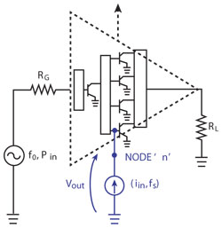
Figure 1 Small-signal sinusoidal current source connected at a particular node of the circuit for stability analysis.
To address these issues, the STAN tool offers a stability analysis technique for microwave circuits that is valid for small-signal and large-signal regimes. This patented technique, which has been developed by the University of Basque Country and the French Space Agency (CNES) is able to detect and determine the nature of oscillations, such as parametric oscillations in power amplifiers that can be, for example, a function of the input drive signal. Knowledge of the type of oscillation mode facilitates the insertion of stabilization networks, with a good balance between the required oscillation avoidance and maintaining the original circuit performance.
The stability analysis used is based on the pole-zero identification technique. This technique has the benefit of being applicable to DC, small and large-signal stability analyses within a similar methodology and, from the simulations obtained, in commercial CAD tools. Figure 1 shows a small-signal sinusoidal current source connected at a particular node of the circuit for stability analysis.
Integration in CAD environment
The first step is to select a node of the circuit to be analyzed and to connect a small current source to this node. Then a linear or a nonlinear simulation using a commercial simulator is performed in order to obtain the frequency response. Simulation templates are available for both Agilent ADS and AWR Microwave Office simulators to easily facilitate this implementation in the CAD environment.
The second step is to identify the frequency response to obtain the transfer function and the associated poles and zeros. This step is done using the STAN tool which, starting from a text file exported from the simulator, enables easy identification and analysis of the results. Figure 2 illustrates a pole-zero plot.
Node Selection and Oscillation
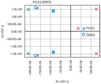
Figure 2 Pole-zero plot.
In simple circuits with a clear feedback structure (some amplifiers, oscillators, etc.) any node should serve for the analysis. However, for more complex circuits such as multi-stage power amplifiers, at least one analysis per stage is highly recommended.
Analysis at several nodes is not necessarily a drawback of the technique because relevant information about the nature of the oscillation and the place in which it is being generated can be extracted from such analysis. A multi-node simulation can be completed, and with the obtained results it is then possible to determine the kind of oscillation mode and its location in the circuit. This information will help the designer to define the most suitable stabilization strategy.
Parametric Analysis
Multi-parameter analysis can also been performed, that is to say analysis sweeping a circuit parameter. This can be used for verification under various conditions or checking the critical resonances, sweeping the input drive power, the load impedance or any parameter inside the circuit. Tracking the evolution of critical poles allows a better understanding of the circuit dynamics and helps determine which parameter has an influence on the circuit stability. Figure 3 plots poles versus input power showing an oscillation from 13 dBm of input power.
Parametric analysis is also extremely useful for the optimization of the stabilization networks. It facilitates finding the best trade-off between stabilization of the circuit and its RF performances.
New Design Approach
Commonly used techniques for the stabilization of microwave circuits are empirical and can be too conservative. Designers often over-design their circuits, guard-banding designs by including excessive safety margins. Such over-designing leads to ICs that are more conservative than necessary in power, size and performance specifications.
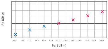
Figure 3 Poles versus input power showing an oscillation from 13 dBm of input power.
Using the STAN tool from the early design stages leads to an enhanced approach in the design of RF and microwave circuits. STAN is used throughout the optimization process to help reduce the amount of stabilization networks that deteriorate the RF performances at the fundamental frequency of operation, while preserving similar stability margins. Thanks to the identification speed of the tool, it even opens up the possibility of performing Monte-Carlo stability analysis, in order to check the stability versus the manufacturing process variation.
AMCAD Engineering,
Limoges, France
+33 (0) 555 040 531,
www.amcad-engineering.com