
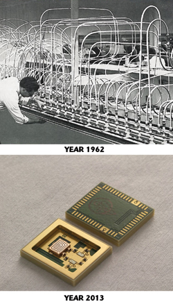
Figure 1 Coaxial time delay unit miniaturization.
The PolyStrata® fabrication process has been outlined in literature, including a 2008 article in Microwave Journal.1 This process is exclusive to Nuvotronics but it is offered as a platform for commercial and military customers to design into next-generation systems. While the PolyStrata process defines a general 3D hardware micro-manufacturing platform, the resulting air-dielectric micro-coax transmission line technology is in itself a significant new wave guiding medium worth understanding and exploring for many applications.
This article compares attenuation performance and other parameters of PolyStrata air-coax to other popular media. Linear behavioral models based on round coax are provided for two sizes. Attenuations of competing transmission line media are compared to PolyStrata coax with all relevant model parameters provided. While it is not possible to provide a comparison of every type of transmission line, this article provides a practical reference for engineers to analyze specific situations, weigh potential benefits that PolyStrata coax might hold for a given problem, and determine why and when it should matter to a particular design.
It goes without saying that attenuation of a transmission line is important, however, it takes on extreme importance in situations where long lines are required, as in feed networks and time delay networks. Figure 1 compares a time delay unit from 1962 to what is possible today using Nuvotronics PolyStrata coax technology. The 2013 solution is no larger than the coax connectors that were used in the 1962 network.
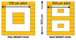
Figure 2 Cross-sections of full and half height PolyStrata coax.
Two “Standard” Coax Geometries
Principally, there are two geometries for PolyStrata coax, which are shown in Figure 2. The 700 and 500 µm pitch between adjacent conductors assumes shared vertical walls of 100 µm thickness, which are possible in most cases. Other dimensions and geometries are possible, but these two sizes have become the typical “standard dimensions” upon which a passive device library has been constructed. In creating long delay lines, it is desirable to meander a delay line into a compact layout. Long meandered microstrip lines can cause problems due to coupling between adjacent segments. Grounded coplanar waveguide can solve the coupling issue when isolation vias are properly used but pitch between lines is several millimeters at best. The ability to share a 100 µm wide wall is an important consideration for this process, which can meander lines in three dimensions and maintain impedance control even in vertical transitions. When expressed in the time delay packing density figure of merit of nanoseconds/cubic centimeter, currently no other transmission line technology obtains the performance of PolyStrata coax:
- Full height with shared walls: 5.2 ns/cubic centimeter (1.5 meters coax/cc)
- Half height with shared walls: 14.3 ns/cubic centimeter (4.2 meters coax/cc)
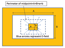
Figure 3 TE11 mode for rectangular coax.
In practice, these figures of merit can be approached, but layout considerations such as input and output RF launches reduce what can be practically achieved.
Cutoff Frequencies
Two slightly different undesirable TE11 modes are possible in rectangular coax,2 but a very simple model of TE11 can estimate cutoff. TE11 for round coax cuts off when the midpoint between the conductors is approximately a wavelength in the chosen dielectric. TE11 can be approximated in rectax by the same calculation, as illustrated in Figure 3.
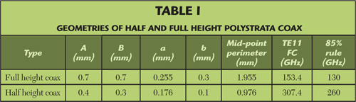
A widely accepted engineering practice restricts operation to below 85 percent of calculated TE11 cutoff frequency. For full height and half height PolyStrata coax, critical geometries and estimated TE11 cutoff frequencies for fifty ohm lines are provided in Table 1. Applying the 85 percent rule, PolyStrata half height fifty ohm lines can be used to 260 GHz, and full height to 130 GHz. Note that 1 mm air coax, which has become a standard in test and measurement systems, has a TE11 cutoff of ~129.5 GHz and is used to 110 GHz, following the 85 percent rule. The platform can also provide precision waveguide for millimeter and sub-millimeter-wave frequencies.
Practical Impedance Ranges
Impedance ranges of PolyStrata coax are generally greater than what is available in other media. The following practical limits should be considered:
- 15 to 110 ohms (full height coax)
- 35 to 105 ohms (half height coax)
Impedance as low as 8 ohms has been demonstrated.
Transmission Line Attenuation Mechanisms
Attenuation in transmission lines includes losses due to metal conductivity, dielectric loss and radiation. In this article we consider losses due to metal and dielectric. We can ignore surface roughness (a component of metal loss) in the PolyStrata process as it has excellent surface finish inside and out. In ideal coax, attenuation due to radiation is zero; in this process, very small radiation occurs from “release holes” used to remove sacrificial photoresist. However, attenuation due to radiation is low enough so that it can be ignored compared to metal and dielectric losses, and it is an order of magnitude lower than radiation losses in CPW or microstrip transmission lines. In very large PolyStrata delay lines that are not packaged in shielded enclosures, release holes can be a minor source of electromagnetic interference that can be essentially eliminated using a coating system Nuvotronics has developed.
Attenuation Due to Dielectric Loss Tangent (αd)
Although PolyStrata structures are often referred to as “air coax,” users should be aware that there is a non-zero dissipation factor (DF, a.k.a. loss tangent or tan(δ)) which would not be the case if the center-conductors were somehow magically suspended in air. Dielectric dissipation results from dielectric straps, which are used to position the center conductor. Although they occupy just a few percent of the overall volume between center and outer conductors, the dielectric support material presents appreciable bulk loss. Overall a good composite number for the dissipation factor is 0.001. Efforts are underway to reduce dielectric attenuation while maintaining a robust transmission line.
In all transmission lines, dielectric attenuation (αd) is known to be proportional to frequency, whereas attenuation due to metal conductivity (αc) is proportional to Œ  . At increasing frequency, loss tangent eventually dominates attenuation of a transmission line compared to metal loss. Loss tangent attenuation is geometry dependent in that it only occurs where electric field is contained in the lossy material (i.e., dielectric loss of microstrip will be lower than stripline if they use the same dielectric material). In coax, 100 percent of the E-fields are in dielectric. In CPW, ~50 percent of E-fields can be considered within dielectric, while in microstrip, perhaps 70 percent are in dielectric. There is no size-scaling advantage for dielectric loss, fat coax will have the same dielectric loss as thinner coax provided they use the same dielectric fill.
The equation for dielectric attenuation in TEM media is:
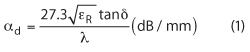
Note that lambda refers to free-space wavelength in the equation. Rearranging the equation, loss tangent attenuation is revealed to be directly proportional to frequency, SQRT(εR) and tan(δ):
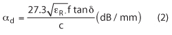
For quasi-TEM media such as CPW or microstrip, the “εR” term can be substituted with Keff (effective dielectric constant) with approximate results. Microstrip on 100 µm thick GaAs (εR=12.9, Keff~9), dielectric loss increases by a factor of three compared to media with εR close to unity (like PolyStrata), if they have the same loss tangent. Thus, higher εR leads to higher dielectric attenuation per length.
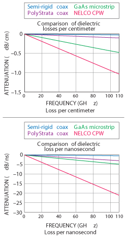
Figure 4 Loss tangent attenuation for various transmission lines.
When expressed in dB/ns (as would be important in time delay), it is interesting to note that dielectric attenuation is no longer a function of εR but is still very much proportional to tan(δ) and frequency:
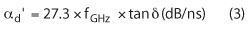
Thus, there is no dielectric attenuation disadvantage to having high εR in time delay systems, at least not directly. However, higher εR results in increased conductor losses, as conductor size shrinks to maintain required characteristic impedance.
Figure 4 shows modeled dielectric attenuation expressed both in dB/cm and dB/ns, for four transmission line media. Semi-rigid coax with PTFE dielectric has the most favorable dielectric loss, but PolyStrata coax is a close second. The “NELCO” CPW board has a tan(d) of 0.007 so it is not a good choice for long networks. Microstrip on GaAs has almost 5× higher dielectric loss per unit length than PolyStrata coax, but when expressed in dB/ns, it is only 60 percent higher. Looking at dielectric loss alone is important in understanding relative performance of media, but metal conductivity loss must always be considered, and at lower frequencies metal conductivity is the dominant attenuation effect.
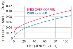
Figure 5 Comparisonof surface resistivity
for ENIG over copper (1 μm gold over 1 μm
nickel) and pure copper.
Attenuation Due to Metal Conductivity (αd)
Structures that use pure copper metallization are typically passivated using electroless nickel/immersion gold (ENIG). One micron of gold provides a single skin depth at 6 GHz, at lower frequencies, much of the conduction that would have been possible in gold or copper is prevented by the nickel underplate. Figure 5 compares surface resistivity of ENIG over copper to that of pure copper across frequency. To a first order, when ENIG is used to passivate copper, surface resistivity doubles at 5 GHz, and is 25 percent higher at 100 GHz (see RF sheet resistance spreadsheet of multi-metal systems for calculating values3). Attenuation due to metal conductivity is not necessarily controlled by one surface resistivity value, because conductor surfaces are not always uniformly plated (in PWBs just the top surface of copper might be ENIG). Often, when a soldered joint is sought, the top gold is just a “flash” (,0.1 micron) which can increase loss substantially as more E-field penetrates to the lossy nickel layer. A coating system has been developed for PolyStrata coax that passivates copper with thin organic materials. This system preserves the conductivity of copper and offers a significant advantage over ENIG in the process.
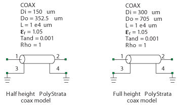
Figure 6. Linear behavioral models for 50 ohm Polystrata coax in AWR's
Microwave Office.
Coax Behavioral Models
Behavioral models for 50 ohm PolyStrata coax lines in AWR’s Microwave Office (MWO) are shown in Figure 6. “Rho51” in MWO implies resistivity of copper, or 1.68E-9 ohm-m. Similar models can be employed in other EDA software using the values provided for εR and tan(δ). Note that different characteristic impedances can be modeled by changing center conductor diameter (leaving outer conductor diameter fixed), subject to the impedance limitations previously defined.
Figure 7 provides a plot of attenuation from DC to 110 GHz, of full and half height PolyStrata coax, predicted by Nuvotronics’ behavioral model, for 50 ohm transmission lines. Here is where metal conductivity and dielectric loss tangent can be seen to have different effects depending on frequency band. At low frequency (10 GHz for example), half height coax has almost exactly double the loss of full height coax, which might be expected as its center conductor has exactly ½ the same cross-section perimeter and ac is doubled. At increasing frequency, loss tangent attenuation adcomes appreciably into play and is equal for both styles; thus at 110 GHz, half height coax’s disadvantage is only ~60 percent compared to full height.
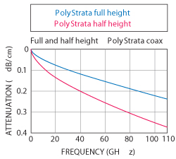
Figure 7. Modeled attenuation of full and half height
PolyStrata coax.
Coax Attenuation Comparison
Here we have chosen several relevant transmission line media and plotted their attenuations compared to PolyStrata. Note that there is some controversy in the values of tan(δ) for many of the materials, reported values vary widely; the reader must be further warned that all material properties are functions of temperature, frequency, and manufacturing quality or purity.
The attenuation plots provided have different frequency stop points for different media. Generally accepted frequency limits of each media could be due to higher order modes, rules of thumb, or even MIL-standards, and are debatable. Although the plots all stop at 110 GHz, full height PolyStrata coax can operate to 130 GHz, while half height coax can operate to 260 GHz. In all cases, the potential effects of surface roughness were ignored. A complete list of material properties and geometries used to model all of the data in this report is available here.
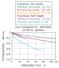
Figure 8. Attenuation of PolyStrata vs. microstrip
on Alumina.
Versus Alumina Microstrip
Alumina has been the go-to media of hermetic modules for forty years. Properties of alumina are dependent on purity and polishing; the comparison in Figure 8 assumes 99.5 percent purity. Below X-Band, PolyStrata offers no loss advantage to alumina, provided the tallest alumina is used (20 or 25 mils). The frequency region where PolyStrata makes a big difference starts at 20 GHz, where the height of alumina must be reduced to 15 mils. Upper frequency bounds were determined to be where alumina microstrip height is 10 percent of a wavelength.
Versus CPW on Organic Boards
Organic boards are used successfully in many RF applications. One popular media is grounded CPW. Nelco N40004 and MEGTRON 65 are improved versions of the ubiquitous fire-retardant FR-4. FR-4 is almost never used for microwave networks as the loss tangent is as high as 0.01. Nelco N4000 material is a popular choice up to 12 GHz, MEGTRON 6 is a newer and more expensive material from Panasonic that can be used to 40 GHz. Figure 9 compares each material to PolyStrata coax. In each case, the CPW media is sized at ~7 mil dielectric thickness, with line widths on the order of ~11 mils and gaps at ~4 mils which will perform without spurious mode problems beyond 20 GHz. Given the chosen geometries, PolyStrata has a substantial attenuation advantage over both technologies, at all frequencies.
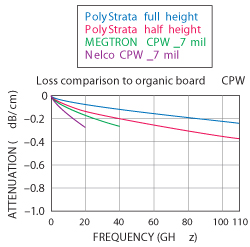
Figure 9. Attenuation of Polystrata coax vs. CPW-G on
advanced organic materials.
If the organic boards must support wirebonding, ENIG is used. We used conductivity of gold in the models that generated the loss plots, which may underestimate loss at low frequency. Dielectric loss due to solder stop can be considerable, and is ignored in the models, the reader is warned never to place solder stop over critical CPW runs on organic boards.
Versus Microstrip on GaAs/GaN
One of the original claims for the DARPA 3D-MERFS program6 was that PolyStrata coax is one-tenth the loss of MMIC transmission lines, but the exact ratio depends on the geometries of both media and the frequency that is being compared. In Figure 10, four and two-mil GaAs and GaN MMIC microstrip are compared to PolyStrata coax. It is assumed that the GaN MMIC uses SiC substrate at εR 510, versus GaAs at εR 512.9. Many values of loss tangent have been reported for both materials. Frequency sweeps stop where four-mil microstrip media become 1/10 wavelength tall. As if GaN did not need another advantage over GaAs, attenuation is less because silicon carbide’s lower εR results in wider microstrip traces.
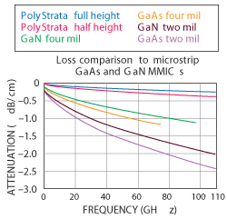
Figure 10. Attenuation of PolyStrata coax vs.
microstrip on GaAs and GaN.
Work on MMIC time delay networks has been reported, but printing delay lines greater than 50 ps on GaAs or GaN could be regarded as a misuse of expensive media.
Versus Semi-Rigid Coax
Semi-rigid coax is often used for delay lines. It comes in many diameters, the closest diameters to PolyStrata coax are 020 (mils) and 034 which correspond to half and full height PolyStrata coax in terms of cross-section. However, the minimum bend radii of semi-rigid coax cannot compete with a system where a U-turn is possible on a 250 µm radius.
MIL-DTL-17 specifies semi-rigid cable, in diameters as low as 0.034 inches. Impedance tolerance is given at ±2 ohms, and max recommended frequency is 20 GHz, although these cables should support higher frequencies before TE11 occurs (see Table 2). Delay accuracy of custom semi-rigid cables has been quoted at ±20 ps7 and may change after temperature cycling due to dielectric expansion or relaxation. This is the equivalent of cutting cables with 4 mm accuracy in length. PolyStrata coax is formed with micron tolerances and will provide better time delay accuracy in all applications compared to semi-rigid delay lines.
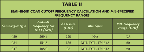
Figure 11 compares attenuation of three sizes of semi-rigid coax to PolyStrata coax. The MIL-spec cables have been plotted to twice their specified frequency range (to 40 GHz) and the 020 semi-rigid is plotted over the full 110 GHz band. Semi-rigid 047 has a loss advantage but is significantly taller than full height PolyStrata coax; it can be seen that 020 semi-rigid has similar loss properties to half height PolyStrata coax, while 034 semi-rigid is similar to full height PolyStrata coax. In the comparison, the conductivity of copper for semi-rigid coax was used, although the center-conductor is copper-clad steel; at low frequencies, the full loss of semi-rigid cable may not be captured by the model. MIL-spec semi-rigid coax is specified to operate from -40° to 100°C. PolyStrata coax can operate over a much higher range of temperatures with less delay variation.
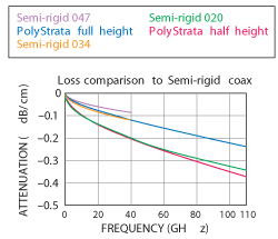
Figure 11. Attenuation of PolyStrata coax
vs. semi-rigid coax.
For geostationary space applications, every ounce of mass sent into orbit is worth its weight in gold. Each meter of semi-rigid 034 is specified at 4.17 grams. PolyStrata half height delay lines have been fabricated that weigh just 0.81 grams per meter, a 5× advantage. When expressed in grams/nanosecond delay (important in TDU applications), the advantage narrows but is still significant: semi-rigid 034 is 0.87 gr/ns, while half height PolyStrata coax has been demonstrated at just 0.24 gr/ns, an almost 4× advantage.
Versus Stripline in LTCC
LTCC has become a popular choice for products up to W-Band, owing to the evolution of materials such as Dupont’s 9K7.8 However, dielectric and metal losses are higher than PolyStrata (see Figure 12). For delay lines or feed networks, LTCC is at a sizable disadvantage. The resistivity of metal that is printed as a thick film will never be as low as pure copper; in the case of 9K7, it is 3× higher. The loss tangent of 9K7 system is excellent at 0.001. Note that surface roughness was not considered in any of the media and reference data for the material properties and geometries of various interconnect systems used in this article are available online at www.mwjournal.com/polystratareference.
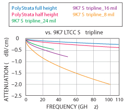
Figure 12. PolyStrata coax vs. stripline in LTCC.
Conclusion
PolyStrata coax matters as a transmission line medium to applications where low RF loss is of paramount importance. Critical examples include power amplifier combiners and applications where long runs of low-loss transmission lines are needed (time delay units and feed networks). The attenuation advantage of the process depends on frequency and what other media are considered. Below X-Band, other solutions may hold advantages. PolyStrata coax also matters when volume and mass are design drivers, such as in time delay units or feed networks aboard satellites. Other trade advantages such as direct transitions to MMICs, thermal dissipation and 3D integration may be covered in future articles.
References
- Z. Popovic, S. Rondineau, D. Filipovic, D. Sherrer, C. Nicholas, J.M. Rollin and K. Vanhille, “An Enabling New 3D Architecture for Microwave Components and Systems,” Microwave Journal, February 2008.
- R. Reid, E. Marsh and R. Webster, “Micromachined Rectangular-Coaxial Transmission Lines,” IEEE Transactions on Microwave Theory and Techniques, Vol. 54, No. 8, August 2006.
- RF Sheet Resistance, www.microwaves101.com, accessed August 26, 2013.
- Nelco N4000 data sheet.
- MEGTRON 6, Advanced Materials & Technologies, December 2010.
- J. Evans, “3-D Micro Electro Magnetic Radio Frequency Systems (3-D MERFS) and other DARPA RF MEMS Programs,” Compound Semiconductor Integrated Circuit Symposium, November 2006.
- Microcoax app note, Coaxial Delay Lines: Design Considerations, created November 16, 2007.
- Dupont 9K7 data sheet