
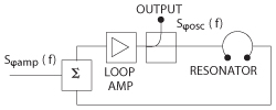
Figure 1 Oscillator general block diagram.
This article describes a 4 GHz ultra low noise oscillator with a frequency-locked loop (FLL) that incorporates a frequency detector (FD) employing a conventional dielectric resonator having an unloaded quality factor (Q) of 8000. Its single sideband (SSB) phase noise spectral density of –153 dBc/Hz at 10 kHz frequency offset from the carrier is superior to the best traditional crystal oscillators scaled to the same output frequency. The oscillator was built using low-cost, commercially available off-the-shelf parts.
Modern high frequency synthesizers typically employ phase-lock-loop (PLL) architectures that rely on the phase noise characteristics of a lower frequency reference oscillator. A good example is the FSW-0010 synthesizer (a.k.a. QuickSyn) manufactured by Phase Matrix1 that produces a signal with phase noise nearly equal to its multiplied internal reference with minimal added noise degradation. It is common to use a crystal oscillator as a reference, which provides the benefits of low phase noise and high frequency stability. Although performance varies from vendor to vendor, the single-side band (SSB) phase noise of the best state-of-the-art crystal oscillators is generally between –170 and –180 dBc/Hz at 10 kHz offset from a 100 MHz carrier. This scales to –130 to –140 dBc/Hz at 10 GHz.2,3 Reference oscillators with lower phase noise can be built by employing higher frequency, higher Q, sapphire or metal cavity resonators.4 Although they provide outstanding noise performance, these oscillators are limited in their application due to size and cost constraints. Alternatively, oscillator phase noise can be reduced using frequency-lock-loop (FLL) stabilization, which suppresses the phase noise generated by the oscillator components such as the loop amplifier and phase shifters.5,6
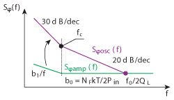
Figure 2 Graphical representation of Leeson's equation.
Oscillator Phase Noise
Oscillator phase noise at the output of the loop amplifier (see Figures 1 and 2) is defined by Leeson’s equation.7-9
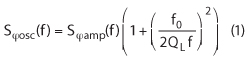
where f0 is the oscillation frequency, QL is the resonator loaded quality factor and Sφamp(f) is the phase noise spectral density of the loop amplifier, which in most cases can be approximated by the following expression:
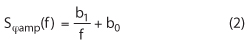
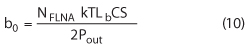
where b1 is the flicker constant (approximately 10-12…10-10) defining the flicker phase noise component8 and b0 is the relative level of the thermal noise component at the output of the loop amplifier:8,10
NF is the noise figure of the saturated loop amplifier and Pin is the saturated power at the amplifier output divided by the feedback losses.
Equations 1 to 3 indicate simple methods for reducing phase noise:
- Increase the power at resonator input.
- Optimize the feedback losses.
- Reduce the amplifier noise – thermal and flicker.
- Increase the quality factor of resonator.
Unfortunately, these methods can work in opposition to each other. For example, increasing output power may (and normally will) result in its noise figure and flicker noise increase. Amplifier-induced noise can be reduced by keeping the amplifier out of compression, e.g., by inserting a limiter at the input;9,10 however, this leads to a higher equivalent noise figure for the amplifier chain that limits overall noise improvement. A well-known practice is to simply use a low flicker-noise amplifier such as a BJT or HBT.12
Feedback losses are at least 6 dB due to resonator coupling factors, which are commonly set to 0.5 in order to fulfill the minimum phase noise condition.13 In reality, however, feedback losses can easily exceed 9 to 10 dB due to additional losses in the coupling and phase balancing components. Effective methods for phase noise reduction are normally limited to the use of high-Q resonators, low noise amplifiers and optimum resonator coupling.8,13
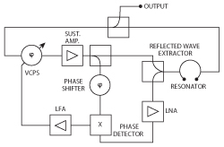
Figure 3 Oscillator with FLL.
Phase Noise of an FLL Stabilized Oscillator
The advantage of an FLL (see Figure 3) is that it minimizes both the noise figure and flicker-noise while maintaining high power in front of the resonator.5-9 The specific coupling with the resonator is important. The coupling coefficient at the resonator input must be set to βin»1 in order to achieve minimum reflection and to assure a low signal level at the LNA input. The reflected signal is commonly extracted by the means of a directional coupler or a ferrite circulator. It is amplified and compared with the signal extracted directly from the oscillator loop using a conventional phase detector (PD). The low frequency PD output is used to reduce the phase noise arising in the oscillator loop.5,6,8
The minimum achievable phase noise level at frequency offsets smaller than the resonator’s half-bandwidth is given by the following expression:14,15
where NFD is the FD noise figure equal to the LNA noise figure for high-gain amplifiers.14 Comparing Equations 1 and 4, note that the last one is free of the limitations imposed by the resonator losses as well as by the loop amplifier phase noise.
A modification of the FLL approach employs a voltage controlled oscillator (VCO) stabilized by means of an external FD using a high-Q resonator. This enables further improvement and optimization of the main oscillator and the discriminator circuitry. A drawback of this technique is the possibility of FLL lock failure due to a frequency offset between the main oscillator and the external FD. This can be avoided with a narrowband (essentially fixed-frequency) main oscillator that is pre-tuned to the discriminator frequency.
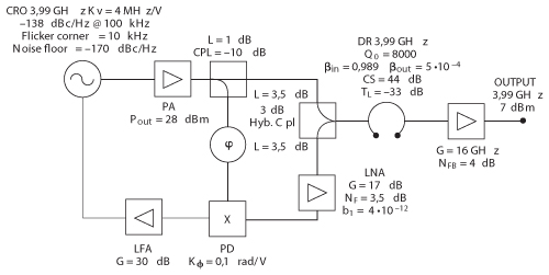
Figure 4 Oscillator stabilized by a frequency discriminator.
Theoretical Model
The structure of the discriminator stabilized oscillator is shown in Figure 4. Phase noise at the buffer output is defined by the following expression:
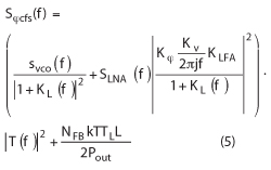
where Svco(f) is the VCO phase noise, SLNA(f) is the LNA phase noise, KV is the VCO tuning sensitivity, Kφ is the PD gain, KLFA is the low frequency amplifier (LFA) gain, NFB is the output buffer noise figure, TL is the resonator transmission loss, L is the transmission loss from the loop amplifier output to the resonator input (4,5 dB) and KL(f) is the FLL transfer function given by:
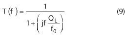
where Br(f) and T(f) are the resonator phase noise transfer coefficients given by:8,14
Here CS is the magnitude of carrier suppression at the LNA input equal to the resonator’s reflection loss,
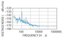
Figure 5 Voltage noise at the phase detector output.
where Q0 is the resonator unloaded quality factor and βin is the input coupling coefficient.
In the case of a high-gain LNA, the SLNA(f) is defined by Equation 2 with
where Lb is the additional loss introduced by the reflected wave extractor.
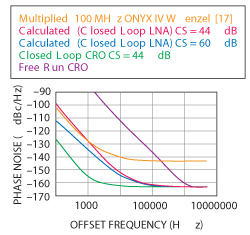
Figure 6 Calculated phase noise.
Unfortunately, flicker-noise parameters of the LNA and mixer are not necessarily specified by their manufacturers. Therefore, an accurate phase noise calculation is impossible without a preliminary characterization of the FD noise floor. This defines the overall noise introduced by the phase shifter, LNA and the mixer and enables calculation of phase noise for the entire oscillator. The noise spectral density measured at the PD output is shown in Figure 5.
Assuming the PD gain is 0.1 V/rad, the measured FD noise floor is –151 dBc/Hz at 10 kHz offset. On the other hand, considering that the LNA input power is –22 dBm and its NF is –3 to –3.5 dB,16 then according to Equation 3, the calculated LNA phase noise is –151.5 to –152 dBc/Hz. This is in good agreement with the above measurements. Based on these results, the main source of FD phase noise is the LNA. The flicker constant (b1) is determined to be 4×10-12.
Equation 5 shows that system phase noise is proportional to the LNA-induced phase noise divided by the offset frequency at offsets within the resonator half-bandwidth; therefore, the flicker corner of the system phase noise will be the same as that at the flicker corner at the LNA output. As the CS value increases, the phase noise floor at the LNA output increases and the flicker corner decreases. Theoretically, the flicker corner of system phase noise can be infinitely small but it requires an infinitely high CS, which is difficult to achieve and hold. A CS of about 40 to 50 dB is a practically achievable number.
The total phase noise at different CS values and phase noise of some elements are shown in Figure 6. This figure also includes the phase noise of the best crystal oscillators17 multiplied to 4 GHz.
Measurement Results
The oscillator is assembled on a round PCB placed on top of the dielectric resonator chamber as pictured in Figure 7. It uses low cost, commercial off-the-shelf parts. Its diameter is 50 mm and is 40 mm high. For reliable frequency lock after power-on, a narrowband CRO is utilized. The CRO frequency is set with a DC-voltage offset applied to the feedback low-frequency amplifier to ensure frequency lock.
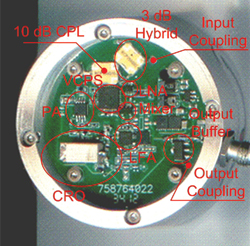
Figure 7 Oscillator assembly.
Two identical oscillators with a frequency difference of about 10 MHz were constructed to measure phase noise. The oscillator signals were mixed down in an external mixer and phase noise at the mixer IF output was measured. Assuming that both oscillators exhibit similar noise performance, phase noise at the IF output was corrected by 3 dB and is shown in Figure 8. For comparison, calculated performance is also shown for a sapphire loaded cavity oscillator (SLCO)14 and a dielectric resonator oscillator (DRO)18 scaled to a carrier frequency of 4 GHz.
One can see that use of the discriminator with a dielectric resonator enables phase noise performance that is 15 to 18 dB lower than the simple DRO. The designed oscillator nevertheless has phase noise 10 dB higher than the SLCO because it is limited by the unloaded Q (Q0=8000) of the DR.
Conclusion
A low noise oscillator based on a dielectric resonator frequency discriminator has been designed using low cost, commercial off-the-shelf components. Phase noise performance of the oscillator exceeds that of a multiplied crystal oscillator and is comparable to performance of more expensive and bulky sapphire and metal-cavity resonator oscillators. Further improvements are possible using dielectric resonators with higher Q-factors and by replacing the hybrid coupler with a ferrite circulator. Furthermore, frequency tuning can be implemented to compensate for thermal instability by applying an external reference signal as needed. The oscillator can be used as a low noise reference source in modern frequency synthesizers and other applications where low phase noise is a key specification.
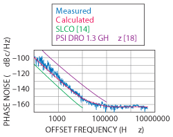
Figure 8 Measured and calculated phase noise compared with a DRO and SLCO.
Acknowledgment
The author would like to thank Alexander Chenakin from Phase Matrix Inc. for his review and valuable feedback and Nicholas Shtin from SMK Electronics Corp. for his review and help in the creation of the mathematical models.
References
- A. Chenakin, “Novel Approach Yields Fast, Clean Synthesizers,” Microwaves & RF, October 2008, pp. 101-110.
- Agilent Technologies, E8257D/67D, E8663D PSG Signal Generators, www.agilent.com.
- Pascall Electronis Ltd., XMN & XMNP Series 200 MHz – 3 GHz Ultra Low Noise Signal Sources, www.pascall.co.uk.
- A.S. Gupta, D.A. Howe, C. Nelson, A. Hati, F.L. Walls and J.F. Nava, “High-Spectral-Purity Microwave Oscillator: Design Using Conventional Air-Dielectric Cavity,” IEEE Transactions on Ultrasonics, Ferroelectrics and Frequency Control, Vol. 51, No. 10, October 2004, pp. 1225-1231.
- Z. Galani, M.J. Bianchini, R.C. Waterman, R. Dibiase, R. Laton and J.B. Cole, “Analysis and Design of a Single-Resonator GaAs FET Oscillator with Noise Degeneration,” IEEE Transactions on Microwave Theory and Techniques, Vol. 32, No. 12, December 1984, pp. 1556-1565.
- E.N. Ivanov, M.E. Tobar and R.A. Woode, “Ultra-Low-Noise Microwave Oscillator with Advanced Phase Noise Suppression System,” IEEE Microwave and Guided Wave Letters, Vol. 6, No. 9, September 1996, pp. 312-314.
- D.B. Leeson, “A Simple Model of Feedback Oscillator Noise Spectrum,” Proceedings of the IEEE, Vol. 54, No. 2, February 1966, pp. 329-330.
- E. Rubiola, Phase Noise and Frequency Stability in Oscillators, Cambridge University Press, Cambridge, UK, 2009.
- D. Scherer, “Generation of Low Phase Noise Microwave Signals,” Hewlett Packard RF & Microwave Measurement Symposium and Exhibition, September 1981.
- W. Tanski, “Development of a Low-Noise L-Band Dielectric Resonator Oscillator,” IEEE International Frequency Control Symposium Digest, June 1994, pp. 472-477.
- A. Chenakin, “Phase Noise Reduction in Microwave Oscillators,” Microwave Journal, October 2009, pp. 124-140.
- J. Cressler, “SiGe HBT Technology: A New Contender for Si-Based RF and Microwave Circuit Applications,” IEEE Transactions on Microwave Theory and Techniques, Vol. 46, No. 5, May 1998, pp. 572-589.
- J. Everard, Fundamentals of RF Circuit Design with Low Noise Oscillators, John Wiley and Sons Ltd., UK, 2001.
- J.M. López Romero and N. Shtin, “Development of Ultra Low Phase Noise Microwave Oscillators at CENAM,” Simposio de Metrología, October 2008.
- D. Tsarapkin and N. Shtin, “Performance Limits of Microwave Oscillators with Combined Stabilization,” XVI European Frequency and Time Forum (EFTF) Proceedings, March 2002.
- RF Microdevices, SGA3563Z, DC to 5000 MHz, Cascadable SiGe HBT MMIC Amplifier Data Sheet, www.rfmd.com.
- Wenzel Associates Inc., Onyx Series Rugged Oven Controlled Crystal Oscillator, www.wenzel.com.
- P. Stockwell, D. Green, C. McNeilage and J.H. Searles, “A Low Phase Noise 1.3 GHz Dielectric Resonator Oscillator,” IEEE International Frequency Control Symposium, June 2006, pp. 882-885.
Andrew Gorevoy received his Dipl.-Eng. degree from Tomsk State University of Automated Control Systems and Radioelectronics, Russia, in 2007. Since then he has been with research and production company Micran, Tomsk, Russia. He is presently senior engineer in the frequency synthesis group at Micran T&M department, where he leads the development of advanced oscillators and frequency synthesizer products for radar, test and measurement applications. His professional interests include microwave frequency generation, conversion components and subsystems