In most countries, the 60 GHz band is allocated for unlicensed use with up to 7 GHz of bandwidth (57 to 64 GHz in the U.S. and Korea, and 57 to 66 GHz in Japan and Europe, as examples). This is 7 to 9 GHz of spectrum for use in unlicensed applications. As a point of comparison, the 2.4 GHz unlicensed band in the U.S. is 83.5 MHz wide (on the order of 1 percent of the bandwidth available at 60 GHz). The applications that can be supported by such wide bandwidths are multi-gigabit communications for backhaul links, high definition uncompressed video transmission and high resolution radar systems, to name a few.
Integrated circuits (IC) are now available that can operate up through the 60 GHz millimeter- wave spectrum. Typical RF ICs that operate at the lower frequencies can be built into standard IC packaging such as SOIC, QFN and TSSOP. As the frequency of operation increases and into the realm of millimeter waves above 30 GHz, the problems of bond wire self and mutual inductance, parasitic capacitance and PCB trace parasitics start to dominate and limit performance. In order to provide useable components at millimeter waves, some vendors provide a built-in antenna, such as a patch antenna, that is directly connected with very short traces to the IC die pads in order to reduce the parasitic effects. In order to reduce the parasitic lead effects, flip-chip mounting technology is also used.
The problem of getting 60 GHz energy on and off the die is not trivial, and special consideration must be given to creating efficient designs that can facilitate easy development at the component level. Since the antennas that are typically used in fully packaged solutions are small and fairly low-gain with associated wide beam patterns, the resulting operating distance that can be achieved is quite short (on the order of 10 m or less). These compact, short range antennas work fine for applications such as indoor wireless links, small radar sensors or even as high-bandwidth versions of near-field communications. But many applications require longer range requiring highly directional, larger aperture antennas. High-gain antennas significantly increase operating range while reducing multipath and interference.
The most efficient method for interconnecting or coupling a variety of different millimeter- wave antennas is to use industry standard waveguide flange couplings. For the 60 GHz band, the EIA designated waveguide size is WR15 (which covers 50 to 75 GHz), and the standard flange is designated as the UG-385/U. 60 GHz researchers and developers need to connect external antennas, of any arbitrary size and gain, to the RF front end of the system. Efficiently coupling the signals at these frequencies into and out of the waveguide port from an integrated circuit is a challenge. There are vendors that have successfully built MMIC type amplifiers, mixers and other separate millimeter-wave functions using ceramic substrates packaged in precision machined waveguide block type assemblies. These blocks are good for basic research in a laboratory environment, but not for an integrated and low-cost solution intended for commercial product development.

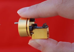
Figure 1 Vubiq waveguide module (a), dimensions (b) and flange close up (c).
Low Cost Waveguide Module
To answer the need for easily attaching a variety of antennas to low cost integrated 60 GHz transmitters and receivers, Vubiq Inc. introduced its 60 GHz waveguide modules, the V60TXWG2 transmitter and V60RXWG2 receiver. Figure 1 shows a photo and a dimensional drawing of the Vubiq waveguide module.

Figure 2 V60TXWG2 transmitter block diagram (a) and V60RXWG2 receiver block diagram (b).

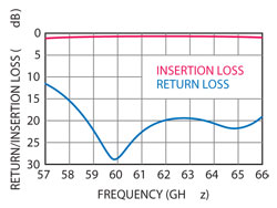
Figure 3 Waveguide module insertion loss and return loss across the 60 GHz band.
The waveguide module design incorporates a simple low frequency I/O connector (Samtec ST4) for interfacing the required voltages, reference clock and modulation signals (up to 2 GHz response). The modules incorporate SiGe BiCMOS radio chips with the ability to produce +12 dBm P1dB transmit output power, 6 dB receive noise figure and take up less than one cubic inch (<16 cm3) of total volume. The on-chip synthesizer produces RF carrier frequencies from 56.5 GHz up through 64 GHz in 500 MHz channel step increments. The transmitter up-converts I and Q input signals in the form of analog baseband capable of up to 1.5 GHz modulation bandwidth. The receiver down-converts from 60 GHz to analog baseband I and Q signal outputs. In addition, the receiver incorporates selectable AM and FM detectors. See Figure 2 for the transmitter and receiver IC block diagrams. The Vubiq waveguide module design exhibits very low loss and is a connectorized module with DC and modulation signals applied at the input signal connector, with modulated 60 GHz energy produced at the output waveguide flange.
Figure 3 shows the return loss and insertion loss modeled from the actual IC die output pads to the waveguide flange port. Less than 1 dB loss is incurred in the module across the band from 57 through 66 GHz. Careful design, modeling and design for manufacturing (DFM) were applied throughout the process of creating these modules. The result is a set of high performance 60 GHz transmitter and receiver modules that are designed for high-volume production.
A Comparison: Coax versus Waveguide at 60 GHz

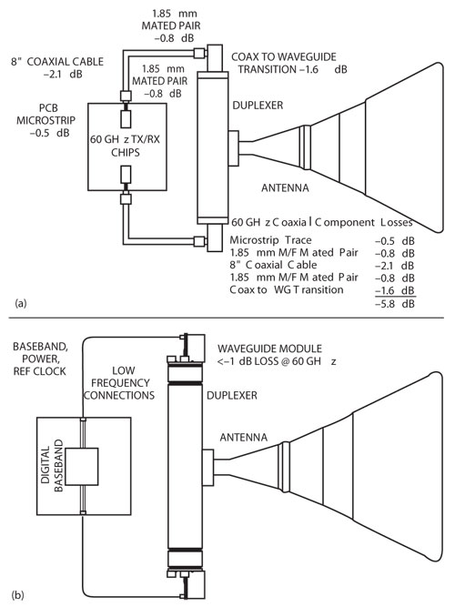
Figure 4 Typical loss values of coaxial components (a) and waveguide module (b) in a 60 GHz backhaul link.

Figure 5 Waveguide modules with duplexer/antenna (a) and close up of the TX module (b).
It is critical to keep losses as low as possible at millimeter-wave frequencies in order to achieve the best signal-to-noise ratio in communications systems. At 60 GHz in particular, oxygen absorption adds specific attenuation at 15 dB/km (at sea level) to the traditional free space loss equation. For point-to-point links, every dB counts to work over the longer ranges required in applications such as high-bandwidth gigabit backhaul.
As a general comparison, coaxial connectors, transmission line and coax-to-waveguide transition components exhibit significant losses and are expensive. The types of coaxial connectors that are used up to 67 GHz are the 1.85 mm threaded “V” connector and the newer MMPX series, which is an unthreaded snap connector. A quick analysis shows that using a coaxial transmission line can add 5 to 6 dB of additional losses at each end of a link, totaling to more than 10 dB of additional link budget loss as compared with the waveguide approach. Figure 4a illustrates the loss build up for a coaxial component design of a full duplex link at 60 GHz for backhaul applications. The total additive losses for the link are in excess of 10 dB, which would be equivalent to losing half the range capability for a typical 300 meter link.
The Vubiq waveguide module brings the source of the 60 GHz energy directly to the waveguide aperture which translates to significantly reduced losses at the system level. Figure 4b shows how the interconnections between the digital baseband board and the millimeter-wave front-end waveguide module of a full duplex link terminal are limited to the lower frequency baseband signals, power and reference clock and do not include more complex RF interconnections. The loss incurred at 60 GHz in this approach is exactly the loss of the waveguide module which is less than 1 dB.
In Figure 5a, a full duplex RF front end is shown with a waveguide transmitter module, waveguide receiver module, a wideband duplexer and a 35 dBi horn antenna. This arrangement is designed for use in a full duplex, gigabit Ethernet link with greater than a 500 meter range at 1.25 Gbps. Figure 5b shows a close up of the transmitter module interfaced to the WR15 flange of the duplexer.
Development System for Quickly Getting On the Air
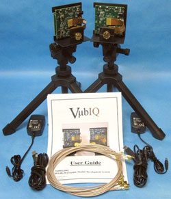
The waveguide modules are controlled via a Serial Peripheral Interface (SPI) port. Users who want to have a fast, out-of-the-box experience for getting 60 GHz on the air in minutes can also obtain the Vubiq Development System (V60WGD02 – see Figure 6) that provides a USB powered interface set of boards and a simple software control GUI that allows for easy setup in the lab.
The TX and RX boards in the development system provide power supply regulation, reference clock generation and a USB to SPI interface to the waveguide modules. Each board has MCX coaxial connectors for easy interfacing to analog baseband signals. Each board contains a low phase noise reference clock (285.7 MHz) but can also use an external reference source for phase locking the TX and RX together if desired.

Figure 6 V60WGD02 development system.
The aperture produces a pattern equivalent to about a 7 dBi gain antenna, which is approximately a 70 degree wide beam pattern. Bench top testing of various modulation schemes and bit rates can be done in this manner with easy TX to RX alignment since the patterns are so wide. For longer range testing, a directional gain antenna significantly increases the gain. Directional adjustment is made at the tripod head for pointing.
The control GUI that comes with the system is a graphical, easy-to-use screen for completely setting up the transmitter and receiver functions. The GUI screen also provides monitoring of synthesizer lock, module and board temperatures, and power supply voltages.
The future of millimeter-wave technology is accelerating into the present by the introduction of highly integrated silicon that can operate into the spectrum above 30 GHz. With the standards bodies and regulatory agencies promoting the latest technologies for millimeter-wave operation, in particular the unprecedented global bandwidth available for unlicensed operation at 60 GHz, the future of broadband wireless networking is well in hand. High performance must be matched with low cost, practical components for the 60 GHz band – and Vubiq is playing a vital role in providing much needed components and engineering development systems.
Vubiq Inc.,
Aliso Viejo, CA
(949) 226-8482,
www.vubiq.com
