
The development and upgrade of SIGINT ISR platforms is a time consuming and costly endeavor that must balance two somewhat conflicting requirements. On one end, the mission critical nature of a deployed system maximizes the importance of fielding a proven system, often creating a preference for existing systems that have been successful in the past. On the other end, the need to address rapidly evolving threats, many of which are based on quickly changing commercial technology, requires that a SIGINT ISR system must incorporate enough state-of-the-art functionality to adjust to new requirements. Exacerbating this challenge is the difficulty of testing ISR systems during development and integration. The final success of a SIGINT ISR solution is completely dependent on how it performs whendeployed under real world conditions where the RF spectrum is increasingly crowded. As a result, the developer and/or buyer are often forced to rely on fully testing systems only once they are installed on the target platform.
While Field Tests have the benefit of replicating in-service conditions, complete control of the RF spectrum during flight is not possible. SIGINT ISR systems are tasked to operate against many environments including terrestrial point-to-point communication, SATCOM, wireless networks and a wide variety of commercial and military systems. Frequency reuse results in a densely overlapped spectrum when viewed from an ISR platform. Spectrum efficiency and interference mitigation have led to complexity of waveforms that are difficult to collect and decipher even when they are clearly received by ISR systems. The variety of transmitters and power levels as well as density leads to very high dynamic range requirements. A further complication is that most ISR platforms operate transmitters that are in-band with desired collection. With the variety of possible end-use environments and the expense and time required for testing on the target platform, Field Testing is best reserved for systems that have already been thoroughly tested against realistic collection environments representing multiple potential scenarios.
A-T Solutions, in collaboration with National Instruments (NI), has demonstrated the ability of a modular commercial-off-the-shelf (COTS)platform to generate realistic, complex test scenarios with signals that reflect relative motion, spectral overlap, frequency and time offset. This system can be used in a laboratory environment, in-lieu of field test installed on a platform. This article will briefly discuss the forces in the commercial sector that are driving applicable capability in COTS test equipment, the architecture of the COTS instrumentation selected and the results of the collaboration to produce a realistic SIGINT ISR collection environment code-named LoBSTER (Low-Band System Test and Evaluation in Real-time).
A Test Environment That Benefits from Advances in Commercial Technology
At the end of 2011, the number of wireless mobile subscriptions in the world had exceeded 5.9 billion. Approximately 1.2 billion of these connections are capable of accessing third generation (3G) networks and the increased data rates and functionality they provide.1 The constant evolution of the use of wireless spectrum as methods of communication, whether it be voice, video, data, emergency information or command and control, is driving tremendous investment by commercial industry to create an infrastructure capable of supporting development of new wireless devices.
In test, this has translated to the need to provide new test methodologies and system architectures that enable faster product development cycles from concept to reliable product – meeting the requirements that are driven by current wireless standards but with the capability to quickly adapt to new technology. Over the last few years, this has resulted in various trends driving modern wireless test systems. Two of the most relevant trends in reducing the cost of testing SIGINT ISR systems are the development of modular instrumentation platforms based on COTS technology and software-defined instrumentation.
Modular Instrumentation Based on COTS Technology
By modularizing the key functional blocks of traditional instrumentation, modular instrumentation platforms are built to take advantage of the rapid advancement of COTS technology in various functional areas.
- Processing elements – integration of different computational elements (heterogeneous computing) allows for the tasks comprising wireless test applications to be executed on the element offering best performance. General Purpose Processors (GPP), field-programmable gate arrays (FPGA), Graphical Processing Units (GPU) and digital signal processors (DSP) continue to be driven by Moore’s law, offering increasing computational horsepower.
- Bus technologies – high speed point-to-point interconnects offering guaranteed bandwidth and deterministic latency. Modern instrumentation buses, such as PXI Express, enable individual modules to transfer data at rates of GBs/sec.
- Baseband elements – A/D and D/A components continue to evolve, enabling wider bandwidths and increasing dynamic range.
- RF front ends – multiple implementations from super-heterodyne to wideband homodyne architectures provide options for maximizing RF performance in different areas. Separate local oscillators (LO) ease frequency/tuning constraints and enable phase synchronous, multi-channel systems.
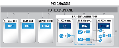
Figure 1 Example of a modular RF instrumentation system.
One such modular instrumentation standard is PXI. Figure 1 shows an example of a high level block diagram of a modular RF vector signal generator in a PXI chassis with an embedded host computer, programmable FPGA module and external RAID storage interface. The RF signal generator itself is broken into three separate modules: an IQ modulator that translates an RF signal from baseband to RF, an arbitrary waveform generator that drives the IQ modulator with a user-defined waveform and an LO module. The other modules in the system provide shared resources for the RF generator to use, such as the display connected to the embedded controller or the massive storage available in the external RAID system, or additional resources to expand the functionality of the generator, such as the FPGA module adding real-time processing to create waveforms on the fly. The modular nature of the platform allows for test systems to be easily reconfigured for additional channels of RF generation, greater computational power for embedded processing and larger data storage while maintaining the original investment.
Software-Defined Instrumentation
Test environments are moving from closed, fixed capability to open, software-defined functionality. This has been driven by the need to test increasingly complex devices that are themselves defined more and more by software. Software-defined instrumentation allows a test environment to become a dynamic system that adopts functionality defined by the user.
In the context of wireless test, the ability to embed user-created software into the instrumentation platform provides the capability to reuse work done in the design stage of a wireless product or standard. During the development phase of new wireless standards, comprehensive simulation is done to determine how a receiver will perform under deployed conditions. Models are created for the protocol, the physical layer and the actual environment. Software-defined instrumentation provides a methodology to move these models from the simulation domain to hardware to generate and receive physical signals. Final functionality could include custom measurements, generation of RF signals previously recorded or generated from off-line modeling, and/or implementation of a full software defined radio or complex channel model to simulate a deployment environment in real time.
An important consideration with software-defined instrumentation is the potential complexity of programming the different elements within the system. A software environment/tool chain that simplifies the integration of hardware with abstraction, supports heterogeneous computing with a common programming paradigm for the different computational elements and is compatible with models generated from other languages and tools, is critical.
An ideal way to address this challenge is by using the graphical system design approach, which provides an integrated software and hardware platform that scales across design, simulation, deployment and test, from desktop to embedded systems. An example is NI LabVIEW system design software, which is the heart of the graphical system design approach, as it uses a graphical dataflow language to abstract hardware control functions. This unified abstraction combines user interfaces, models of computation, math and analysis, input/output signals, technology abstractions, and various deployment targets to greatly simplify any system.
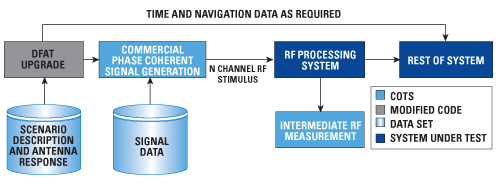
Figure 2 LoBster system architecture.
Architecture of SIGINT ISR Test Platform (LoBSTER)
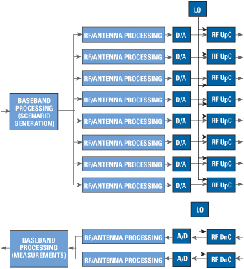
Figure 3 COTS RF subsystem.
A-T Solutions’ LoBSTER is designed for test and integration of complex ISR systems, providing multiple channels of RF stimulus conditioned to replicate the signal normally received at the antennas of the system(s) under test (SUT). Input to more than one collection platform can also be provided. The RF stimulus to the SUT is based on a scenario that describes the movement of collection platforms and the location and activity of emitters. Scenario time and navigation data are provided to the SUT as well as the ability to monitor and record their RF processing. Emitter signals can be defined strictly from simulation or can incorporate previously recorded signals. Output signals are individually adjusted for collection platform motion, propagation conditions, collection antenna patterns, angle of arrival at collection platform, and collection platform separation. LoBSTER provides up to eight coherent channels of RF stimulus with precise control of scenario signals. The overall architecture is given in Figure 2.
In order to generate an accurate representation of a realistic SIGINT ISR collection environment, multiple channels of phase-synchronous RF generation with tight specifications on relative channel-to-channel phase, amplitude and frequency accuracy are required. Using the modular nature of the RF signal generator in Figure 1, LoBSTER consists of up to eight channels of RF upconverters and ARBs driven by a shared LO. Each channel provides up to 100 MHz of generated bandwidth. The RF/antenna signal processing and hardware control necessary to align the channels and maintain precise phase, amplitude and frequency levels is done in on-board FPGAs in the instrument modules. With a shared LO driving all upconverter stages and the PXI backplane driving the sample clocks for the digital-to-analog converters, normal contributors to inaccuracy, such as phase noise from the reference clock, affect each channel equally and therefore cancel out when examining relative channel-to-channel values. Along with the RF signal generation, LoBSTER adds two channels of coherent RF signal acquisition to monitor and record the RF processing done by the SUT. Figure 3 illustrates the high-level diagram of the RF generation and signal processing elements.
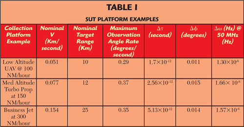
Performance values are derived from analysis of the phenomena to be modeled. The fundamental goal is to create a stimulus environment that will be good enough so that simulated signals will evaluate the performance of the SUT without simulation artifacts becoming a controlling factor in SUT performance assessment. Table 1 shows incremental changes for selected conditions that are comparable to peak value of real collection scenarios, with the delta change assessed at 10 millisecond intervals.
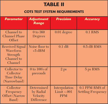
This assessment is made at the point of maximum rate of change for the indicated range and velocity. Using simple stimulus signals, the ability of the COTS RF signal generation hardware to meet the listed accuracies was validated. Derived COTS test system requirements for simulating these real world effects are shown in Table 2.
Recreating the Environment
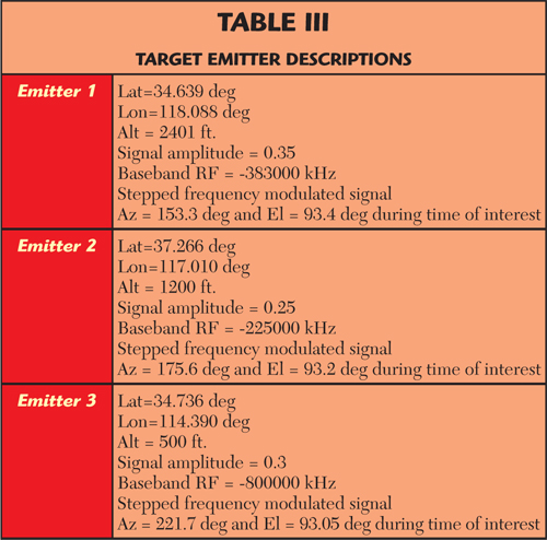
To validate the ability of the final test system to accurately reproduce flight scenarios, a scenario with three airborne ISR systems collecting multiple emitters is created. The scenario is illustrated in Figure 4, with the target emitter characteristics defined in Table 3.

Figure 4 Test scenario geometry.

Figure 5 Spectrum comparison: simulated versus generated RF.
The COTS test system, shown in Figure 3, was used to generate the RF signals from the defined scenario and the output was recorded with a multi-channel, phase-aligned RF measurement system. The results were compared with the original models. Figure 5 displays the spectrum of the simulated data versus the baseband recovered from the actual RF generated from the test system. The blue signals are the original baseband spectra, and the red spectra are the recovered baseband. As will be noted, the spectra are essentially indistinguishable.
To validate that the phase relationships remained consistent between the original models and the generated RF, the MUSIC algorithm2 was applied to the four input channels for platform 1 defined in the scenario shown. Figure 6 depicts the pseudo spectrum which results from covariance and eigenvector analysis of the four channels of baseband data collected by platform 1. This shows three peaks of amplitude when plotted against the 360º range of angles of arrival around the collection platform. In Figure 6, the vertical blues represent the azimuth angle of arrival at platform 1 with pseudo spectrum plotted in red.
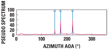
Figure 6 Angle of arrival simulated data.
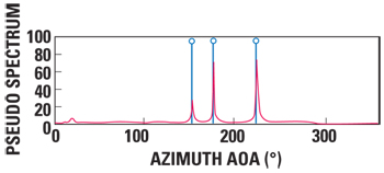
Figure 7 Angle of arrival generated RF.
Figure 7 depicts the results of applying the same analysis to the recovered spectrum after RF conversion. As can be observed, the recovered angle of arrival and pseudo spectrum are essentially identical to that derived from the original simulated baseband. Further analyses included placing a beam former on the signal at 176º and recovering the spectrum. The desired spectrum was isolated and validated to be as simulated.
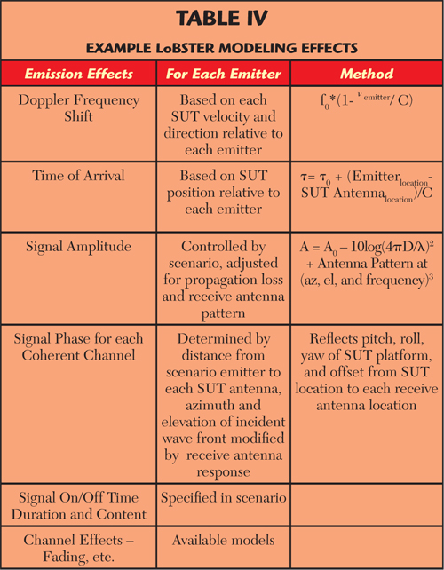
The key functionality of LoBSTER is based on the software Direction Finding Analysis Toolset (DFAT) which provides the key software components to compute incident angles and antenna responses to received signals, so that the SUT receives RF stimulus as though it were from system antennas. LoBSTER also uses the extensive library of geo location modeling codes and scenario simulation to address time offset, frequency shift and channel-to-channel phase offset. Table 4 gives some examples of these.
The signal generator is aligned to the first channel of the suite. This uses the embedded firmware to control the output waveforms, which achieves the necessary adjustment range accuracy and precision as shown. Because the scenario explicitly controls the waveforms, LoBSTER can provide signal environments that are difficult if not impossible to replicate during flight test. These signal environments can be merged with RF signals recorded off air or modeled on platform transmitter output, as desired, to provide a representative RF environment to SUT.
Conclusion
This ability to recreate a realistic SIGINT ISR collection environment in the laboratory can be used throughout system development, integration and verification. With more complete test coverage of real world conditions before Field Test, ISR development schedules are not tied to deployment platform availability and, when ready, the SUT can be installed on the target platform and proceed to operational verification with high confidence against real world environments. The ability of a COTS test environment to evolve efficiently with new technology driven by the commercial sector enables testing future requirements and provides support for ISR system updates, problem resolution, and similar activities over its lifecycle.
References
- International Telecommunications Union (ITU) 2011 Year End Report.
- R.O Schmidt, “Multiple Emitter Location and Signal Parameter Estimation,” IEEE Transactions on Antennas and Propagation, Vol. 34 March 1986, pp. 276-280.
- H.T. Friis, “A Note on a Simple Transmission Formula,” Proceedings of IRE, Vol. 34, No. 5, May 1946, pp. 254-256.
Dave Giles holds a bachelor’s degree from Stanford University, advanced studies and a Juris Doctorate from Santa Clara University. Giles has lead the development of several systems and provided engineering to multiple system developments during his career of more than 40 years in ISR, including software, system design, analysis, and field support. As the lead SIGINT System Engineer for A-T Solutions Colorado office, he leads the development of ISR tools for A-T Solutions.
Sean Thompson holds a bachelor’s and a master’s degree in computer science from Rice University. As the Platform Manager for Aerospace and Defense at National Instruments, he manages the National Instruments (NI) Platform in key application areas within Aerospace and Defense and the business development initiatives for these applications. During his 20-year career at NI, he has served as the Segment Manager for RF and Communications, business development manager for ATE, a field engineer for telecom and military accounts, and the manager of the VXI applications group.