
A compact microstrip lowpass filter using radial stub resonators is developed. This filter is composed of two radial stub resonators that are asymmetrically connected to each other by a stepped impedance structure. This structure results in a very high rejection and wide stopband. The proposed filter with a 3 dB cutoff frequency of 2.07 GHz has been designed, fabricated and measured. Measurement and simulation results are in good agreement.
Microstrip lowpass filters with compact size and high performance find many applications in communication systems for suppressing unwanted signals. These filters appear in various shapes such as a shunt open-stub at the feed point of the center fed coupled-line hairpin resonator, which is used to design a compact lowpass filter with very wide stopband1 and stepped impedance hairpin resonators2 that present wide stopband and high selectivity. A filter has been proposed using a stepped impedance resonator with the assistance of open stubs and short-end coupled lines.3 The stopband characteristics of this filter have improved but it has low selectivity. Another shape is used to obtain compact size and low insertion loss, utilizing a symmetrically loaded radial shape.4 A novel compact Koch shaped electromagnetic bandgap microstrip lowpass filter with wide stopband has been presented.5
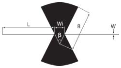
Fig. 1 Layout of the proposed resonator.
Radial stubs have been used to achieve a wide stopband operation and deep rejection through zero point generation.6 Both symmetrically loaded resonant patches and meander transmission lines have been used to achieve compact size and wide stopband.7 The design of a lowpass filter is based on a defected ground structure and stepped impedance shunt stubs8 for suppressing harmonics. A multisection lowpass filter is presented9 where each section is composed of a transmission line and an interdigital capacitor. It has been demonstrated that the passband performance of a microstrip stepped-impedance lowpass filter can be improved by constructing the low impedance sections with fractal shapes, such as Koch and Sierpinski fractal shapes,10 but the transition band of this structure is not sharp. Because of the short comings of the mentioned structures, in this article, a lowpass filter, using radial stub resonators that are asymmetrically connected through a stepped impedance structure, is presented that improves the width and attenuation of the stopband.
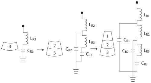
Figure 2 LC equivalent circuit of the radial stub.
Design of the Proposed Filter Structure
The layout of the proposed resonator is shown in Figure 1. This resonator is composed of a transmission line loaded with radial stubs. The dimensions of the resonator are L =7.65 mm, W =0.1 mm, R =4.7 mm, Wi =1.6 mm and β=54°. Figure 2 represents a new LC model for a radial stub. This model is achieved by considering each radial stub to be made of three smaller radial stubs that are connected to each other, thus by modeling each small stub and then connecting these models to each other, the final model is obtained. The LC model of the radial stub resonator is shown in Figure 3.In this model, the central transmission line is described by Lt1 and Lt2 as series inductance and Ct as body capacitance, while LR1 - LR3 and CR represent the inductances and capacitances of the radial stub, respectively.
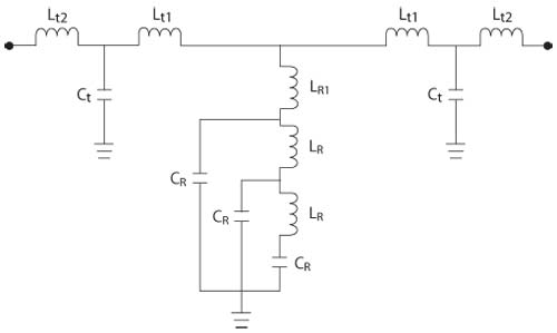
Figure 3 LC equivalent circuit of the proposed resonator.
Figure 4 shows the EM and circuit simulation results of the proposed resonator. The value of the circuit elements that are used in the circuit simulation are: Lt1 =Lt2 =2.2 nH, LR =LR1 =37 pH and CR =0.8 pF. These values are calculated by choosing proper initial values and thenusing tuning techniques in order to match the circuit and EM simulated results. As seen, the circuit and EM simulation results are in good agreement especially at the cut-off frequency. The differences of the responses in the higher frequencies are mostly because of the approximations in the modeling of transmission lines by LC elements and assuming them lossless.
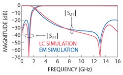
Figure 4 EM and circuit simulation of the proposed resonator.
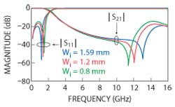
Figure 5 EM simulation of the proposed resonator as a function of Wi.
After introducing the resonator, the effect of dimension variations on the response of the resonator is studied using the LC equivalent circuit to evaluate the importance of each part. The first dimension to be studied is Wi. Figure 5 shows the simulated results of the resonator as a function of Wi. From this figure, it is obvious that by decreasing the value of Wi from 1.59 to 0.8 mm, the transmission zero moves to lower frequencies. This is because this reduction causes an increase in the series inductance of the radial stubs, but decreases the value of the capacitance with respect to ground, according to the area reduction. Table 1 shows the variation of LC parameters as a function of resonator dimensions.
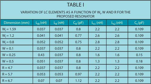
From the table, it can be seen that the overall increase in the value of inductances overcomes the capacitance reduction and as a result, the transmission zero gets smaller. It should be mentioned that in each row of the table, only one of the resonator dimensions is going to be studied and the value of other dimensions are the same as values that were mentioned before.
The second effective dimension is W. Simulated results of the resonator as a function of W are shown in Figure 6. These results illustrate that increasing the value of W reduces the frequency of transmission zero and decreases the insertion loss in the stopband because the series inductance of the transmission line (Lt1 and Lt2) is reduced and the value of LR1 is increased according to the enhanced distance between the radial stubs. Values of the inductances and capacitances are presented in the middle rows of Table 1.
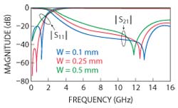
Figure 6 EM simulation of the proposed filter as a function of W.
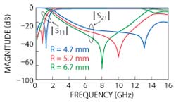
Figure 7 EM simulation of the proposed filter as a function of R.
The third important dimension is R, which when increased, reduces the frequency of the transmission zero because this increases the values of both capacitance and inductance of the radial stubs as seen in the three last rows of the Table 1. Simulated results of the resonator as a function of R are presented in Figure 7 and as seen, these results are as expected.
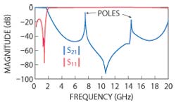
Fig. 8 Response of two connected resonators.
The substrate that is used here has a dielectric constant equal to 2.22, a height of 15 mil and a loss tangent of 0.0009. The simulated S-parameters of the designed resonator depict its wide stopband but low selectivity. To make the roll-off sharper, two units of the proposed resonator can be directly connected to each other; but this causes two harmonics at 7.46 and 14.41 GHz, which are shown in Figure 8.
To solve this problem, the resonators are connected asymmetrically through a stepped impedance cell. This cell is a modified version of an H-shaped, stepped impedance resonator that is tuned to present a wide suppressing range. The layout and photograph of this structure are shown in Figures 9 and 10, respectively. This method doubles the selectivity of the former geometry and suppresses the unwanted harmonics.
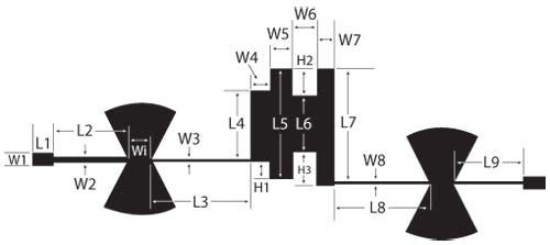
Figure 9 Filter layout.
The correlative dimensions of the proposed filter are: W1 =1.15 mm, W2 =0.45 mm, W3 =W8 =0.1 mm, W4 =W7 =1.17 mm, W5 =W6 =2 mm, Wi =1.6 mm, L1 =2 mm, L2 =6.8 mm, L3 =9 mm, L4 =6.33 mm, L5 =10 mm, L6 =5 mm, L7 =10.66 mm, L8 =8.7 mm, L9 =6.5 mm, H1 =1.8 mm, H2 =2.5 mm, H3 =3 mm.
Simulation and Measurement
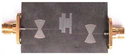
Figure 10 Photograph of the fabricated filter.
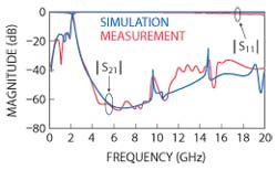
Figure 11 Simulated and measured results for the proposed filter.
The simulation was accomplished using the EM-simulator (ADS) and the measurements were performed using the Agilent network analyzer N5230A. Figure 11shows the simulated and measured results of the filter. As seen, the 3 dB cutoff frequency occurs at 2.07 GHz and a reject-band is achieved from 2.67 up to 20.52 GHz with -24 dB attenuation. The advantage of the proposed filter over the conventional structures can be obtained through the comparison of the bandwidths. The values of improvement are 125, 80, 145, 80, 160, 30, 28 and 260 percent compared to the filters of references 2 to 5 and references 7 to 10, respectively. The attenuation from 3.39 to 14.58 GHz is more than -40 dB, which guarantees the high rejection operation. The insertion loss has a maximum value of 0.2 dB from DC to 1.9 GHz, which indicates a very good passband performance and is better than most of the conventional structures. The return loss is better than 14.6 dB in the passband and is close to 0 dB in the stopband. The transition band is from 2.07 to 2.54 GHz with -3 to -20.12 dB, which is sharper than the filters of references 3 to 5, 7, 8 and 10, with improvements of 50, 25, 53, 40, 3 and 60 percent, respectively. The size of the proposed filter is 44.53 by 15.42 mm.
Conclusion
A compact microstrip lowpass filter is designed, fabricated and measured. The proposed structure is composed of two radial stub resonators and a stepped impedance cell. Simulation and measurement results indicate that the demonstrated filter achieves good performance in terms of high attenuation, very wide stopband and low insertion loss in the passband. This filter has also an acceptable selectivity.
References
- V.K. Velidi and S. Sanyal, “Sharp Roll-off Lowpass Filter with Wide Stopband Using Stub Loaded Coupled-line Hairpin Unit,” IEEE Microwave and Wireless Components Letters, Vol. 21, No. 6, June 2011, pp. 301-303.
- L.H. Hsieh and K. Chang, “Compact Elliptic-function Low-pass Filters Using Microstrip Stepped-impedance Hairpin Resonators,” IEEE Transactions on Microwave Theory and Techniques, Vol. 51, No. 1, January 2003, pp. 193-199.
- C.W. Tang and M.G. Chen, “Design of Microstrip Lowpass Filters with Wide Stopband and High Attenuation,” Electronics Letters, Vol. 46, No. 21, 2010, pp. 1445-1447.
- J. Wang, L.J. Xu, S. Zhao, Y.X. Guo and W. Wu, “Compact Quasi-elliptic Microstrip Lowpass Filter with Wide Stopband,” Electronics Letters,Vol. 46, No. 20, 2010, pp. 1384-1385.
- W.L. Chen, G.M. Wang and Y.N. Qi, “A Compact Wide Stop-band Koch-shaped Electromagnetic Bandgap Microstrip Low Pass Filter,” Microwave Journal, Vol. 50, No. 10, October 2007, pp. 160-166.
- K. Ma and K.S. Yeo, “Novel Low Cost Compact Size Planar Lowpass Filters with Deep Skirt Selectivity and Wide Stopband Rejection,” 2010 IEEE MTT-S International Microwave Symposium Digest, pp. 233-236.
- L. Ge, J.P. Wang and Y.X. Guo, “Compact Microstrip Lowpass Filter with Ultra-wide Stopband,” Electronics Letters, Vol. 46, No. 10, 2010, pp. 689-691.
- J. Park, J.P. Kim and S. Nam, “Design of a Novel Harmonic-suppressed Microstrip Lowpass Filter,” IEEE Microwave and Wireless Components Letters, Vol. 17, No. 6, June 2007, pp. 424-426.
- W.H. Tu and K. Chang, “Compact Microstrip Lowpass Filter with Sharp Rejection,” Microwave Optical Technical Letters, Vol. 15, No. 6, June 2005, pp. 404-406.
- W.L. Chen and G.M. Wang, “Enhancement of Microstrip Stepped-impedance Low-pass Filters Using Fractal-shapes,” Microwave Journal, Vol. 52, No. 7, July 2009, pp. 64-76.
Mohsen Hayati received his bachelor’s degree in electronics and communication engineering from Nagarjuna University, India, in 1985 and the master’s and Ph.D degrees in electronics engineering from Delhi University, Delhi, India, in 1987 and 1992, respectively. He joined the electrical engineering department, Razi University, Kermanshah, Iran as assistant professor in 1993. At present, he is an associate professor within the electrical engineering department, Razi University. His current research interest includes design of microstrip filters for communication systems, application of computational intelligence, artificial neural networks, fuzzy system, neuro-fuzzy systems and electronics circuit synthesis, modeling and simulations.
Sohrab Majidifar received his bachelor’s and doctorate degrees in electrical and electronics engineering from Razi University, Kermanshah, Iran in 2009 and 2011, respectively. His current research interests include design and optimization of microwave and RF circuits and MMIC.
Omid Sadeghi Fathabadi received his bachelor’s and doctorate degrees in electrical and electronics engineering from Razi University, Kermanshah, Iran in 2009 and 2011, respectively. His current research interests include RF electronics, microwave circuit design and modeling, RFIC, MMIC and computer aided design.