
Tahoe RF Semiconductor has introduced the industry's first single chip integrated dual-channel (L1 and L2 bands) GPS RFIC that provides 60 dB of dynamic range in high level interfering environments. The TRFS15011 was developed to address the use of position information in a wide variety of industrial and consumer electronic products where high level interferers may exist. Specifically, because of the impending FCC frequency allocation of the Mobile Satellite System (MSS) frequency band to terrestrial transmitters, commercial GPS receivers may need to operate in environments with high levels of interference. However, commercial GPS receivers currently do not have sufficient dynamic range to mitigate interfering signals from MSS transmitters. One possible solution is to use highly selective filters, but these filters are costly and bulky.
The TRFS15011 reaches new levels of functional integration for high dynamic range GPS receivers. It embodies high levels of integration and combines Tahoe RF Semiconductor's proprietary wireless signal integrity implementation to deliver superior interferer mitigation, lower system cost and eliminate the use of highly selective external filter solutions. The TRFS15011 is currently the only integrated solution that allows GPS receivers to operate in the presence of a high power interferer from terrestrial MSS band transmitters.
Dynamic Range and Potential Interferer from Terrestrial MSS Band Transmitters
The GPS L1 band is from 1560 to 1590 MHz. The proposed portion of the MSS band that will be used by terrestrial transmitters is 1526 to 1536 MHz. The MSS anticipated power level at the transmitter is 32 dBW. With free space path loss, the input of a GPS receiver antenna could be as high as -20 dBm. The L1 signal level difference compared to the interferer can be as much as 90 dB (see Figure 1).
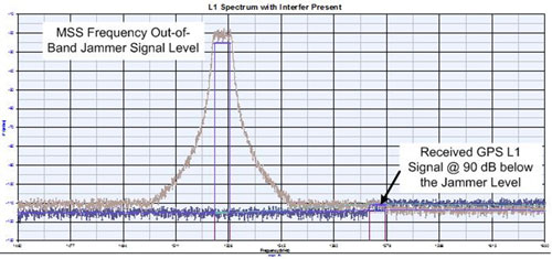
Figure 1 Interferer and GPS signal.
New GPS receivers need to operate in the presence of high level interfering signals. Current GPS RF receivers typically do not operate over more than 18 dB of dynamic range. The embedded filtering in most GPS RF receivers is not sufficient to suppress the interferer and typically requires highly selective external filter solutions to mitigate interference as illustrated in Figure 1.
TRFS15011 Performance
The TRFS15011 integrates high dynamic range 12-bit analog-to-digital converters (ADC) and full receive paths for both L1 and L2 bands. The result is a fully integrated L1/L2 GPS receiver with 60 dB instantaneous dynamic range, providing significant power savings over more discrete systems. Commercial GPS receivers are hampered by low resolution ADCs, which are used in an effort to conserve power. The TRFS15011 solves this problem by including two programmable ADC modes – a low power mode with 3 bits of resolution and a high dynamic range mode with 12 bits of resolution.
Figure 2 FFT of the output with CW tone representing LTE interferer and GPS signal.
Figure 3 FFT of the output with CW tone representing LTE interferer and GPS signal.
Performance in LTE Environments
A single-tone interferer at 1555 MHz was inserted at the front-end of the TRFS15011 along with a low power GPS-like narrowband signal. The signals were down-converted and sampled with the high resolution ADC. The spectral plot of the output shown in Figure 2 represents the typical dynamic range of the TRFS15011 that can be further improved, if needed, with external filtering and baseband processing.
Of more concern is how the receiver processes wider bandwidth signals. A single-tone interferer at 1555 MHz was inserted at the front-end of the receiver along with a low power GPS-like wideband signal. The signals were down-converted and sampled with the high resolution ADC. The spectral plot of the output is shown in Figure 3. The TRFS GPS receiver has enough instantaneous dynamic range to mitigate a high level interferer signal such as the terrestrial MSS.
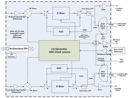
Figure 4 Block diagram.
Device Description
The GPS receiver block diagram is shown in Figure 4. The dual fractional-N synthesizers are completely integrated. The received signal is level controlled by the internal AGC where each signal path includes an RF isolation amplifier, RF mixer, variable gain amplifiers and lowpass filter before the ADCs. There is a low resolution mode with reduced current and lower linearity for low power operation. With minimal external components, the TRFS15011 provides an integrated low cost solution for the interference that is inevitably to come from reallocation of FCC frequency use.
Tahoe RF Semiconductor
Auburn, CA
(530) 823-9786
sales@tahoerf.com
www.tahoerf.com