
Consumers are demanding more from their mobile devices, including increased bandwidth. They have become accustomed to the near universal data connectivity of smartphones and tablets, including applications that continually demand higher and higher data rates. Given the variety of LTE frequency bands, and the range of preferred power levels, RFMD has developed a family of LTE-compatible power amplifiers for data connectivity applications. They are summarized in Table 1.

As can be seen, a wide range of LTE bands can be covered by these PAs. The RF5607, for example, has a large frequency coverage capability of 1.9 to 2.7 GHz. This allows the customer to tune to a desired frequency band within this range. The RF5602 is similar and offers higher output power with less frequency coverage. It can also be efficiently operated at lower power with a reduced Vcc. The linear power listed for each of these amplifiers is for a nominal linearity requirement, and varies depending on the specific modulation used. The RF5612 is intended for uplink applications, the others are primarily intended for the downlink. Many of the amplifiers in Table 1 can also be used in WiMAX applications, typically at higher output powers. RFMD continues to add to its LTE power amplifier family, with higher power levels in particular, soon to be available.
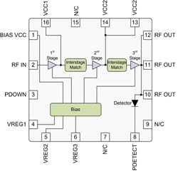
Figure 1 Block diagram of the RF5607.
RF5607
The RF5607 is a versatile member of RFMD's LTE power amplifier family. It is designed using RFMD's InGaP HBT process. The block diagram, Figure 1, shows that this is a three-stage power amplifier with integrated power detection and active bias control. All stages use a 3 × 20 µm dual emitter HBT unit cell. Two cells are used in the first stage. The second and third stages are scaled up to 8 and 32 cells, respectively.
The PA operates in Class AB mode. The second harmonic termination at the output is implemented with an on-chip capacitor and an in-package down bond. The first and second stages are each biased with a two-diode emitter follower. RFMD's proprietary active bias circuit supplies bias to the final stage while providing low impedance for linear operation over the operating range.

Figure 2 The RF5607 LTE downlink PA application board for 2.1 to 2.2 GHz operation.
A unique feature of the RF5607 is that the input and output matching networks are off chip. Interstage matching is broadband to cover the entire 1.9 to 2.7 GHz frequency range. Actual applications are in much narrower bands within this range. Ultimate performance is critically dependent on output match and to a lesser extent on input match. Therefore, optimized matching for specific LTE downlink bands has been developed for implementation off-chip. Figure 2 shows an application board for 2.1 to 2.2 GHz operation. The application boards for other bands are identical, only the values of the matching components change.

Figure 3 Schematic of the RF5607 in a 2.1 -2.2 GHz application.
The schematic, with matching components optimized for a 2.1 to 2.2 GHz LTE downlink is shown in Figure 3. The RF5607 uses a 3 × 3 mm QFN package. ESD protection is included on all pins to both Human Body Model (HBM) and Charged Device Model (CDM) requirements. The exact band of operation is tunable with external components.
The key performance attributes for an LTE power amplifier are power, ACLR and current consumption. Typical power and linearity for the RF5607 are shown in Figure 4. As shown, ACLR remains well below the -44 dBc requirement up to 22 dBm output power. At that point, nonlinearities resulting from the large peak to average power ratio (PAPR) of the modulated signal begin to degrade ACLR. The RF5607 actually provides -45 dBc ACLR.

Figure 4 Typical linearity performance of the RF5607 with a 10 MHz modulated LTE signal at frequencies between 2.11 and 2.17 GHz.

Figure 5 Typical gain and current consumption performance of the RF5607 with a 10 MHz modulated LTE signal at frequencies between 2.11 and 2.17 GHz.
Gain and current consumption are also important power amplifier characteristics. They are shown versus output power in Figure 5. Note how gain is only lightly compressed even at the full LTE rated power of 22 dBm. This highlights the very linear operation that LTE downlinks demand. The current consumption is below 330 mA, even at 22 dBm. Current increases gradually from about 230 mA at quiescence. Since the output stage operates in deep Class AB, the low impedance active bias network allows current to increase so that linearity is maintained as drive level grows.
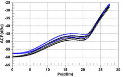
Figure 6 Typical linearity performance of the RF5607 with a 10 MHz modulated LTE signal (blue) and a 5 MHz W-CDMA modulated signal (black) at frequencies between 2.11 and 2.17 GHz.
Figure 6 shows the power and linearity performance of the RF5607 with both a LTE downlink signal and a W-CDMA signal. LTE has a wider modulated bandwidth and a higher data rate than W-CDMA. This increases the linearity demands on the system and on the PA. As Figure 6 shows, this can be directly seen in power amplifier performance. Linearity is 1.5 to 2.5 dB better with the
W-CDMA signal.
LTE provides users with very high data rates in mobile devices enabling streaming multimedia and supporting the growth of social networking and the push to cloud computing. LTE imposes unique system requirements and presents challenges to the power amplifier designer, particularly of the downlink. RFMD has developed a family of products to address these needs. They cover the key downlink frequency bands, provide an ACLR of better than -44 dBc and provide efficient operation with LTE modulation bandwidths of up to 20 MHz.
RF Micro Devices
Greensboro, NC
(336) 664-1233
www.rfmd.com