
The figure of merit (G/T) for a satellite-terrestrial handset is a critical parameter for the link budget calculations, where G is antenna gain, which varies with elevation and azimuth angles, and T is the system noise temperature, which is the sum of the handset receiver and its antenna noise temperatures. For the Terrestar GENUS smart phone, an internal Planar Inverse F Antenna (PIFA) is used1 for satellite communication in the primary service area. In addition, a novel external helix-octafilar antenna has also been designed as the accessory to support secondary service areas.
In the GMR-1 3G Specification,2 the figures of merit for several types of satellite receivers are available with only external antennas. The G/T ratio of the various packet data terminals in the direction of the peak antenna gain under clear sky conditions, with the antenna fully deployed and with no conducting objects in the vicinity of the unit, at 20°C, will exceed the tabulated G/T values at elevations over 20°. For a similar terminal as the GENUS™ smart phone with external antenna (terminal E), the given G/T is -30 dB/K in which the given antenna gain is -1 dB, the antenna noise temperature is 150 K, and the receiver noise figure is 5 dB. The G/T definition2 has caused ambiguity when deriving it using the actual antenna measurements with the handset mechanics, especially about how to define the antenna gain G. It appears that G is a peak antenna gain, but it is unclear which elevation to use, because the peak gain varies with the pointing elevation. If the peak gain is taken at a 20° elevation, the G/T is underestimated, while if the peak gain is taken at a 90° elevation, then the G/T is over estimated. For an internal PIFA, the gain pattern and noise temperature are affected more by the other components around the antenna.
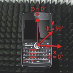
Figure 1 Measurement coordinate system.
In the following section, it can be found that the PIFA radiation pattern is more random in the preferred elevations, that is 20° to 90° and in the whole azimuth plane. In the GMR-1 3G Specification,2 no terminals with an internal antenna are available and it is hard to determine the antenna gain and noise temperature to derive the corresponding G/T. In this article, the work is based on free space antenna measurements with approximately 3° angular steps for both the internal PIFA and the external helix-octafilar antenna. The gain G in G/T is proposed to be a statistical value derived in the preferred elevations from 20° to 90°. The antenna noise temperature is derived by considering the antenna efficiency, loss and the brightness seen by the antenna. Then some proposals are offered, regarding the derivation of the G/T.
Antenna Gain Measurements and Gain Statistics
In the GENUS smart phone, the internal PIFA is located in the upper right corner seen from the back cover. There is an RF port available in the upper right corner as well for using an external antenna. Only one of the antenna ports is available at a time. A user must select the preferred antenna from the handset operating system menus. The gain measurements are done using the coordinates shown in Figure 1.

Figure 2 Gain patterns for the PIFA and helix-octafilar prototypes, forward link (LHCP at 2190 MHz).

Figure 3 Gain patterns for the PIFA #1 and the helix-octafilar #1 at specific elevations, forward link (LHCP at 2190 MHz).
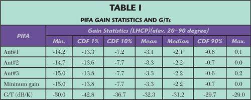
Figure 2 shows the gain patterns (θ = 90°- elevation°) in free space for the forward link (from the satellite to handset) with the left hand circular polarization (LHCP). The first row shows the PIFA patterns, while the second row is for the helix-octafilar prototypes. For both the internal and external antennas, the design objective is to have a good and stable gain pattern in the preferred elevations and also in the azimuth plane. Obviously, the helix-octafilar (being a larger antenna) has better gains in 20° to 90° elevations. Figure 3 shows the gain pattern cuts for Antenna #1 in specific elevations for the PIFA and the helix-octafilar. From the figures, it can be seen that the PIFA gain varies considerably, especially at low elevations. The gain for the helix-octafilar is more stable for a fixed elevation, but the instant gains show a big difference at the low and high elevations. Therefore, from the random PIFA gains, a statistical gain is extracted and listed in Table 1. Then, a reasonable gain is chosen for use in its G/T calculation. For the helix-octafilar, the statistical gain is also extracted and shown in Table 2. From Table 1, it can be seen that the gain repeatability is extremely good for the three PIFA and octafilar prototypes, respectively. The helix-octafilar has better gain statistics than the PIFA, especially in a small Cumulative Distribution Function (CDF), that is approximately 8.6 and 4.7 dB more gain at 1 and 10 percent CDF, respectively.

The System Noise Temperature and G/T
The G/T (dB/K) can be calculated from G -10 log (T), where G is the antenna gain and T is the noise temperature of the system, which is the sum of the antenna and the handset noise temperatures. The antenna noise temperature is derived by considering the antenna efficiency, loss and the brightness seen by the antenna. The sky brightness and how it is seen by the antenna are based on the following assumptions and equations.
- Calculation of the sky brightness (Tsky) by considering:
- Temperature of atmosphere emission: 270 K
- Cosmic background noise: 3 K
- Atmosphere attenuation:
- Oxygen absorption: 0.007 dB/km at 2 GHz
- Height of atmosphere: 10 km.
- Vapor and cloud attenuation are not significant.
- Sky brightness seen by the antenna:3

Where Gmeas is the measured total gain pattern. Finally, the antenna noise temperature can be calculated from:


Where T0 is the physical temperature, which is 290 K. ηtot is the measured antenna total radiation efficiency (total power). ηrefl = 1-|Γ|2 is the reflection efficiency, where Γ is the reflection coefficient, which is calculated by the measured return loss. The total radiation efficiencies4 of the antenna prototypes are calculated and listed in Table 3, from which very good repeatability of the efficiencies for the PIFA and helix-octafilar prototypes can be observed. The total efficiencies for the internal and external antennas are very close. Figures 4 and 5 show the measured return loss of the three PIFA and helix-octafilar prototypes, respectively, used in the calculation of ηrefl. The frequency ranges are 2000 to 2020 MHz and 2180 to 2200 MHz for the return link and forward link, respectively. From Figures 4 and 5, the return losses are very low in the frequency range of the forward link. The return loss at the middle frequency 2190 MHz is selected in the calculations. The final antenna noise temperatures for the prototypes are extracted and shown in Table 3. In the following calculations, the worst 167.1 K and 202.7 K antenna noise temperatures are taken for the PIFA and the helix-octafilar, respectively. The handset receiver noise temperature is 627.06 K using a 5 dB noise figure. The system noise temperatures are therefore 794.16 K and 829.76 K, respectively, for the handset with the PIFA and the helix. In Table 1, the minimum gain G at each column is taken and the final statistical G/Ts are derived and listed in the last row of the tables for the internal and external antennas. The system G/T depends strongly on the antenna gain. The receiver NF is slightly better than 5 dB, based on the measurements conducted on the handset; here a 5 dB NF is taken as proposed.2 From Figures 2 and 3 and Table 1, it is seen that the antenna gains vary with the elevations and the azimuth angles for both the PIFA and the helix-octafilar. For the helix-octafilar, the average G/T (-29.6 dB/K) might be more meaningful, in which the mean antenna gain is -0.4 dB and the antenna noise temperature is 202.7 K.
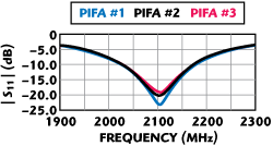
Figure 4 Measured return loss for the PIFA prototypes.
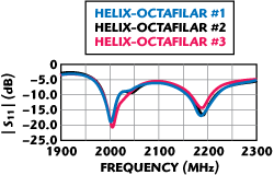
Figure 5 Measured return loss for the helixoctafilar prototypes.
The G/T is proposed to be analyzed statistically as shown in Table 1. It is good to say, for instance, what are the minimum, average, and maximum G/Ts, what is the G/T for a specific CDF point according to the system reliability requirement. However, in practice, one can always ask what is the G/T for the handset, and then the average G/T might be a good value. It should be noted that the G/Ts listed in Table 1 are taken directly from the gain measurements of the three antenna prototypes.
Conclusion
The method and steps for extracting the G/Ts of a satellite handset, with both internal and external antennas, are introduced in this article. The receiver G/Ts, with both an internal and external antennas, were analyzed statistically, while the G/T of the receiver with the external antenna was compared with the result for a similar type of terminal,2 where the -30 dB/K G/T is recommended but with vague definition about how to get this value. In the case of the satellite smart phone with the external antennas, the average G/T is -29.6 dB/K, which is very close to what is suggested.2 For the handset with internal PIFAs, the average G/T is -32.3 dB/K, which is a reasonable value compared to the case with the external antennas. Therefore, the average G/Ts in the preferred elevations can give the better estimations. However, it is good to show the other G/Ts at different CDF points to meet with different system reliabilities. Note that a linear gain should be taken into account in the sky brightness calculations, due to random noise. The suggested antenna noise only has the average sense in the whole 3D space.
Acknowledgments
The authors would like to thank their colleagues from EB, Terrestar Networks (TSN), Hughes Network Systems (HNS) and RKF Engineering for helpful discussions, especially Taavi Hirvonen at EB, Joe Martinet and Carl Ott at TSN, Michael Parr and Juerg Widmer at HNS, Jeffrey Freedman and Ted Kaplan at RKF. Special thanks go to Joakim Granholm, Mari Kähkönen and Ari Immonen at EB for their positive support of this work. The views expressed herein are the authors' and may not reflect the view of EB, TSN and RKF.
References
- X. Zhao, "Internal PIFA Performance Evaluations for a Satellite-Terrestrial Handset," Microwave Journal, Vol. 53, No. 8, August 2010, pp. 84-92.
- "Radio Transmission and Reception," GMR-1 3G 45.005, ETSI TS 101 376-5-5, v3.1.1 (2009-07).
- J. Tervonen, "Radiowave Propagation in Satellite Communications," Helsinki University of Technology, 2004.
- "Test Plan for Mobile Station Over the Air Performance: Method of Measurements for Radiated RF Power and Receiver Performance," CTIA Certification, Rev. 2.1, April 2005.