
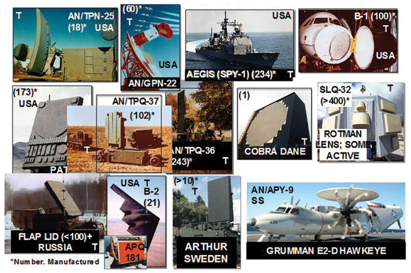
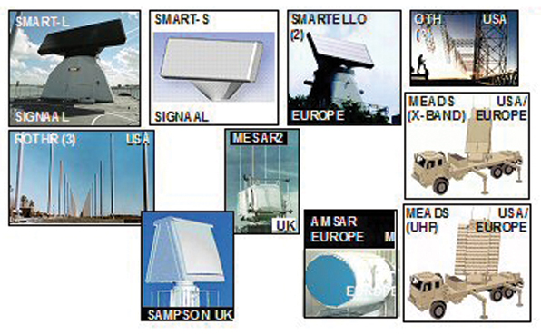
Over the last five decades since the formation of the Microwave Journal, phased-array radars have seen remarkable advances and wide proliferation around the world. This is exemplified in Figures 1, 2 and 3, which give just a few examples of the phased arrays deployed over the last 50 years and under development in recent years. Back in 1957 there were just a few array radars. John Allen’s article, “Array Radars: A Survey of Their Potential and Their Limitations,”24 first published in Microwave Journal in May of 1962, only showed the experimental L-band electronically steerable array radar (ESAR) that was the predecessor of the FPS-85.
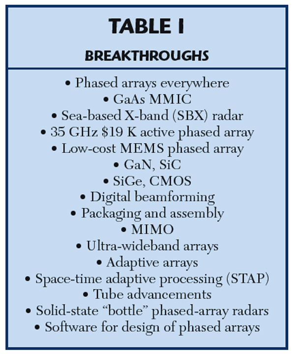
In recent years there have been many important breakthroughs in phased-array technology that bode well for the future of phased-array radars.1,29–36 This article covers some of the past developments and the exciting recent new breakthroughs. The past and recent breakthroughs covered are listed in Table 1.
GaAs MMIC T/R Modules
Defense companies have successfully applied MMICs to AESA radars over the last decade.1 The MMIC APG-79 AESA radar on the F/A-18 E/F allows simultaneous air-to-air and air-to-ground modes (see Figure 2b).25 This means the aircraft can defend itself while at the same time deliver weapons to the target. This is achieved with only a small increase in the cost of the radar over the older mechanically scanned system.(ibid)
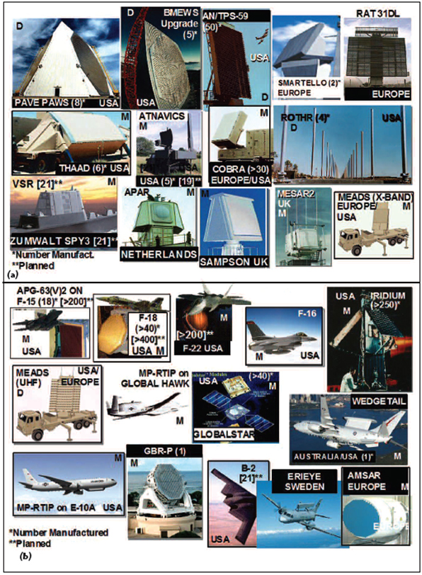
AESA has permitted the Wedgetail AESA L-band arrays to be placed on the top of a Boeing 737-300 for the Royal Australian Air Force without the need of a rotodome, such as used on E-3 Sentry airborne warning and control system (AWACS) aircraft (see Figure 2b). Wedgetail provides 360° coverage; the two back-to-back dorsal arrays provide ±60° coverage broadside while the antenna above them provides endfire coverage of ±30°.
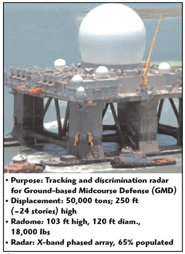
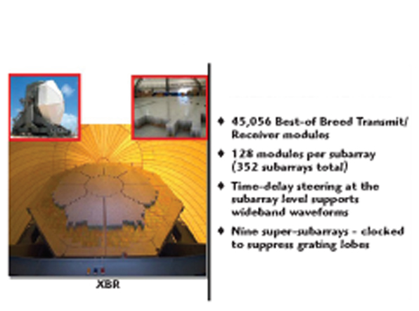
Sea-based X-band (SBX) Radar
The 24-story-high Sea-based X-band (SBX) radar, shown in Figures 4 and 5, is a new wonder of the world.26 Part of the US Ground-based Midcourse Defense anti-ballistic-missile system, it is the most powerful phased-array radar ever produced.
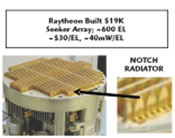
Low-Cost Phased Arrays
Who said AESAs have to be expensive? On Defense Advanced Research Projects Agency (DARPA) funding, the feasibility of a low-cost, $19 K, 35 GHz array was demonstrated (see Figure 6).2 DARPA also funded development of a $10 X-band, 10 mW, single-chip T/R module.3 A 76 GHz photoetched Rotman lens array costing only a few dollars was developed for automotive cruise control.8
Low-Cost MEMS Phased Array
If only we had a low loss phase shifter. Then we could go back to the passive-architecture electronically scanned phased array with one module feeding many phase shifters (10, for example). This could potentially reduce the cost of an electronically scanned phased array by a factor of about ten. Micro-electromechanical systems (MEMS) offer this promise. MEMS switches have improved their reliability by three orders of magnitude over what was reported in October 20033 to a life of 600 billion switches.4,5 There is still need for improvement in the loss. The loss through a four-bit phase shifter used in a 1-D scanned radome antenna space-fed lens (RADANT) is ~1.25 dB. Two lenses are needed for a 2-D scan so that the two-way loss for a 2-D scanned RADANT array would be ~5 dB, but progress is being made.5
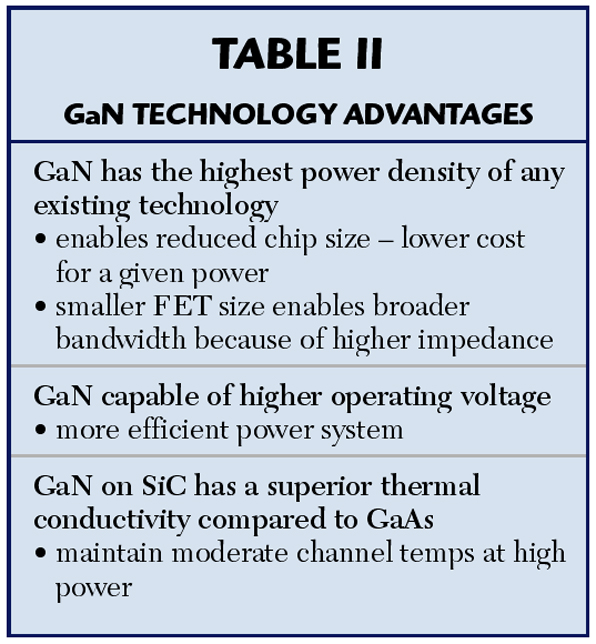
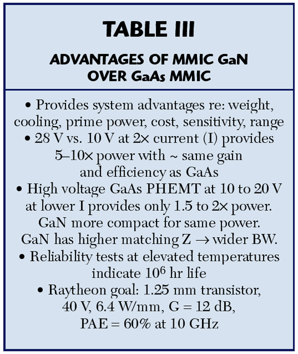
GaN and SiC Chips
Wide bandgap GaN and SiC MMIC chips offer the potential of one to two orders increase in T/R module power (see Figure 7).27 Table 2 summarizes the major advantages of GaN. Tables 3 and 4 compare GaN with GaAs. This technology would make it possible to upgrade an existing AESA by replacing the GaAs T/R modules with GaN or SiC T/R modules having ten times the power. This provides either a ten times improvement in search volume or a 78 percent increase in track range.28
CREE provides commercial SiC hybrid devices putting out 10 to 60 W for up to 4 GHz and GaN hybrid devices putting out 15 to 120 W from UHF to 40 GHz.16 Their goal is to provide in one package 550 W peak and 30 to 40 W average linear power output using a single-stage FET. CREE supports the design of MMIC SiC and GaN chips. For GaN MMIC they provide 60 W saturated from 2.5 to 4 GHz and 25 W saturated from 5 to 6 GHz. See References 16–18 for detailed surveys of state-of-the-art on GaN and SiC.
SiGe Chips
SiGe has the advantage of using Si as a substrate, the technology of the low-cost, commercial integrated-circuit industry and whose extensive resources can be drawn upon. It offers the potential of higher performance at low cost. SiGe does not compete with GaAs with respect to microwave output power or noise figure. It offers low cost and the ability to integrate many functions on a single chip.
In addition to microwave power amplifiers and a low-noise figure receiver on one chip, it can have A/Ds and digital circuitry. It can have CMOS on the same chip, Si CMOS. GTRI is developing a SiGe single-chip T/R module for use in an AESA radar. Its initial design had a peak power of > 50 mW using a two-stage power amplifier (PA). Work is under way to achieve 1 W peak by using three stages.19 The cost per element of an AESA using such a module is expected to be 1/100 that of a GaAs array using high-power T/R modules.19 The low power per module is made up for in a radar by using a larger array, one that possibly folds on itself.
CMOS Chips
CMOS now operates at microwave frequencies. It, too, uses a silicon substrate and is the technology widely used in the computer industry. It holds the promise of low cost and low power for the receiver parts of T/R modules. Like SiGe, it has the advantage of allowing the integration of many functions on a single chip, even more so than SiGe. One chip can have RF, IF, baseband, microprocessor, memory, tunable filters and A/Ds —a system on a chip (SOC). It can be combined with GaAs or GaN for the microwave power amplifier and low noise figure receiver. Using GaN has the advantage of being robust enough that a limiter may not be needed. Si together with CMOS offers the possibility of the integration of many receive and/or transmit channels on a single chip.
Digital Beam Forming (DBF)
DBF has arrived for microwave AESA radars (see Figure 8). It provides many significant advantages over analog beam forming.1 For large arrays I used to say DBF is only being done at subarray. This is no longer true. Elta has done it at the element level for a 2500-element array at S-band, a major breakthrough. Using DBF eliminates the analog combining hardware, analog down-converting and all the errors associated with them. This in turn will lead to ultra-low side lobes. It will allow the implementation of multiple beams pointing in different directions. It will enable the adaptive use of different parts of the antenna for different applications at the same time. It permits simultaneous reduction by a factor of almost two of the transmit RF average search power and search occupancy.6 The cost savings gained from the simultaneous reduction by a factor of almost two of the transmit RF average search power and search occupancy will be far greater than the increased cost due to the greater required signal processing. At the same time, the search angle accuracy is improved by about 40 percent.6 DBF will also permit better adaptive-array processing.

Adaptive-Array Processing
The development of adaptive-array processing represents a major step forward in increasing the usefulness of phased arrays. It started with the invention by P.W. Howells of the side lobe canceller (SLC), which he filed on May 4, 1959 (two years after the formation of the Microwave Journal) and was patented on August 24, 1965 (US Patent No. 3,202,990). This was followed by the seminal work of S.P. Applebaum published as an internal Syracuse University Research Corp. report in August 1966 and then published in the September 1976 special issue on adaptive antennas of the IEEE Transactions on Antennas and Propagation.
The SLC nulls out jammers whose signals come in through the side lobes of the main antenna by using auxiliary antennas placed close to the main antenna. These auxiliary antennas receive the jamming signals. By appropriate processing of the signals received by the auxiliary antennas, it is possible to generate jammer signals having the same amplitude and phase as those coming in through the side lobes. By subtracting these signals from the jammed signals in the main channel the jamming interference is cancelled.
If a phased array is used to form the main beam, elements forming the array can also be used as the auxiliary antennas, thus serving dual use as elements for the main array and as the auxiliary antennas. It is useful to look at the side lobe canceller physically from another point of view. Specifically, the combination of the main antenna and the auxiliary elements with its processing can be viewed as a new antenna system. As such, its antenna side lobe pattern will have nulls in the directions of the jammers while it also has its main beam pointing in the direction of potential targets to be detected, the direction the main beam would point when no SLC processing is used. Very little is published as to which radars used SLC. This is because of the sensitivity of such information.
For a phased array there exists another more effective way for canceling jammers coming in through the side lobes and even in through the main lobe. It is to adjust adaptively the amplitude and phase weights of the array so as to put nulls in the directions of the jammers while maintaining the main beam pointing in the required direction. These amplitude and phase weight adjustments are made based on the jamming signals received by the array and their calculated direction.
This system is known as a fully adaptive array processor. Here again it is useful to view the fully adaptive array from another physical point of view. Just as previously we viewed the SLC as an array that puts nulls in the direction of the jammers, we can now go the other way and view the fully adaptive array processor as a SLC.9,40
Fully adaptive arrays have been too difficult to implement for large arrays up to now, the hardware and the processing load being too great. To reduce the complexity, consideration has been given to doing fully adaptive array processing at the subarray level. This reduces the number of elements from thousands to a few tens. This is what is done on the UK’s Multi-function Electronically Scanned Adaptive Radar (MESAR).41
With the advances of DBF, it is now possible to think of achieving the performance of fully adaptive processing without its complexity. In fact, the equivalent jammer suppression of a fully adaptive array without its computation and transient penalties can be achieved. This can be accomplished with adaptive-adaptive array processing.7 This involves no more than locating digitally where the jammers are, then pointing beams at these jammers (these beams are effectively eigenbeams)9,10,40 and using these beams as side lobe cancellers for the main beam (see Figure 9).

For a 1000-element array having to cope with 10 jammers, we now have to invert a 10 x 10 matrix instead of a 1000 x 1000 matrix and the transient time is reduced by a factor of 100. In a classical fully adaptive array, one does not make use of the location of the jammers. But we can easily determine their location rather than to put on blinders. This method is equivalent to the method of Principal Components.9 The jammers can easily be located by doing a Fast Fourier Transform across the array. This will not locate jammers less than a beamwidth apart, but for many applications it may be good enough. If better jammer cancellation is needed, then two squinted beams about 3/4 of a beamwidth apart can be used for each located jammer. This is because for closely spaced jammers, less than a beamwidth apart, the eigenbeams are sum and difference beams.10
Alternately the Music algorithm can be used.13 Adaptive-adaptive array processing is in the same spirit as the knowledge aided techniques DARPA has been recently funding known as Knowledge Aided Sensor Signal Processor & Expert System (KASSPER),42 which they have applied to Space-time Adaptive Processing (STAP) discussed in the next section.
STAP
STAP is adaptive-array processing of a pulse Doppler waveform. It provides adaptive nulling of ground clutter and jammers on a moving platform. On a moving platform it places a 2-D Doppler-angle null where the clutter is.9 STAP is being used on the new carrier-based E2-D Advanced Hawkeye’s AN/APY-9 radar shown in Figure 1.39 It is used in the littoral environment.39 It can also be used to cancel out ground clutter for a ground-based pulse Doppler radar.37
Packaging And Assembly

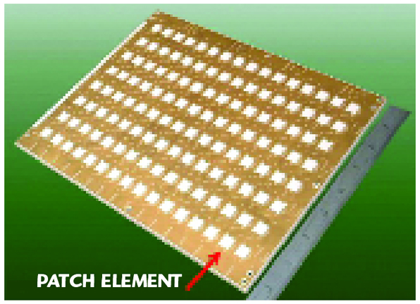
It is now possible to package and assemble active phased arrays having low cost, light weight and small volume. The technique involves the use of commercial printed wiring boards (PCB) and no packages for individual T/R modules. An X-band building-block array of 128 elements and T/R modules was built having a size of 7.4 x 10.1 x 0.21 in.20 (see Figure 10). Its T/R module chips are flip-chip mounted on the backside of the PCB. No case is used for the modules. An approach using low- and high-temperature cofired ceramic (LTCC/HTCC) for the multilayer board is presented in Reference 21. The ultimate in packaging and RF integration is the placement of many receivers or transmitter channels, or both, on a single chip together with their combiner; see Figure 11, where eight receiver channels are integrated onto a single chip.23 This should be possible for some radar applications in the near future. Future plans are to integrate 16 to 32 receiver channels on a single chip and 16 transmit channels on a single chip operating from 30 to 50 GHz.23
MIMO
Lincoln Laboratory at MIT has demonstrated that one can coherently combine two identical radars to achieve a 9 dB increase in sensitivity.11 They first transmit from each radar orthogonal waveforms at the same carrier frequency to achieve the coherence on receive. They next use identical waveforms and vary the phase and delays of the transmitted waveforms to achieve coherence on transmit on the target as well as coherence on receive. This provides a 9° dB increase in sensitivity over a single radar.
By combining N radars they get an increase in sensitivity of N3. Another application for MIMO is for OTH, airborne and ground radars. With MIMO it is possible by transmitting orthogonal waveforms from separate transmit elements or subarrays to identify and isolate the signals from each transmit element or subarray. This then permits the adaptive control at the receiver of the transmitter pattern so as to achieve optimum clutter rejection.15
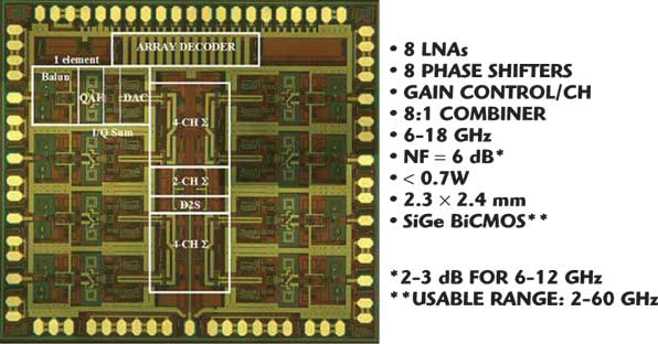
Figure 12 shows this for the case where an array is used for transmit and a single element antenna is used on receive. By using an array on receive as well as on transmit both the transmit and receive antenna patterns can be adaptively controlled for optimum clutter rejection. Nulls can be placed on the transmit antenna pattern as well as the receive pattern in the direction of strong clutter scatterers.
Ultra-wideband Arrays
Ultra-wideband array technology is here. This technology allows the use of one antenna for many different applications at different bands. Raytheon has developed a dual-polarized notch-radiating element that has an instantaneous bandwidth from 1.8 to 18 GHz.3,43 The Georgia Technical Research Institute (GTRI) is developing an array having 33:1 instantaneous bandwidth with potential of 100:1.38
Tube Advancements

Tubes are making major advances.12,14,22 The availability of powerful software now allows the design of tubes without the need for trial and error. It has been recently shown that it is feasible to build an active 2-D phased array at X-band using TWTs that fit within the array lattice, one TWT per element.12
Solid-state “Bottle” Phased-array Radars
The new E-2D radar uses a solid state “bottle” transmitter. Its range is 350 nmi.39
Software for the Design of Phased Arrays
Powerful software is available now (like HFSS, PARANA and CST) that allows the prediction of the performance of antennas to very high accuracy without the need for costly trial and error constructions and measurements. An array designed in the mid ’70s required much trial-and-error and measurements. Today it can be designed without trial-and-error to a small fraction of a dB using Ansoft’s HFSS.
Acknowledgment
I thank Raymond Hale, Colin Whelan and John DeFalco of Raytheon Co. for their input on GaN, SiC, SiGe and CMOS.
References
1. E. Brookner, “Phased Arrays and Radar: Past, Present and Future,” Microwave Journal, January 2006, pp. 24-46; see also International Symposium on Phased-array Systems and Technology, Boston, MA, October 2003, pp. 1–11.
2. T. Clark, “Low-cost Cruise Missile Defense (LCCMD),” DARPA web site, August 24, 2005.
3. L. Corey, International Symposium on Phased-array Systems and Technology, Boston, MA, October 2003.
4. L. Corey, GTRI, private communication.
5. J. Maciel, Radant Tech. Inc., private communication; see also J. Maciel, J.F. Slocum, J.K. Smith and J. Turtle, “MEMS Electronically Steerable Antennas for Fire Control Radars,” 2007 IEEE Radar Conference, April 17–20, 2007, Boston, MA.
6. R. Davis and R. Fante, IEEE Transactions on Antenna & Propagation, July 2001, pp. 1043–53.
7. E. Brookner and J. Howell, “Adaptive-Adaptive Arrays Processing, IEEE Proc. April 1986, pp. 602–04.
8. M. Russell, et al., IEEE Trans. of MTT 12/97, pp. 2444–2453.
9. J.R. Guerci, Space-Time Adaptive Processing for Radar, Artech House Inc., 2003.
10. W.F. Gabriel, “Adaptive Arrays: An Introduction,” Proc. IEEE, Vol. 64, No. 2, February 1976, pp. 239–272.
11. S. Coutts, K. Cuomo, J. McHarg, F. Robey and D. Weikle, “Recent Distributed Coherent Aperture Measurements for Next Generation BMD Radar,” 2007 IEEE Radar Conference, April 17–20, 2007, Boston, MA.
12. B. Levush and E.J. Dutkowski, “Vacuum Electronics: Status and Trends,” 2007 IEEE Radar Conference, April 17–20, 2007, Boston, MA.
13. H. Gu, “Angle-Tracking Adaptive Array: Adaptive-Adaptive,” 2007 IEEE Radar Conference, April 17–20, 2007, Boston, MA.
14. R.J. Barker, J.H. Booske, N.C. Luhmann, Jr. and G.S. Nusinovich, Modern Microwave and Millimeter-wave Power Electronics, Wiley-Interscience and IEEE Press, 2005.
15. G.J. Frazer, Y.I. Abramovitch and B.A. Johnson, “Spatially Waveform Diverse Radar: Perspectives for High Frequency OTHR,” 2007 IEEE Radar Conference, April 17–20, 2007, Boston, MA.
16. Milligan, et al., RadarCon-2007.
17. Kopp, RadarCon-2007.
18. Rosker, RadarCon-2007.
19. Mitchell, et al., RadarCon.
20. Puzella and Alm, RadarCon-2007.
21. S. Al-Taci, MCIC, Un. College London.
22. E. Brookner, “Phased Array and Radar Breakthroughs,” RadarCon-2007.
23. Koh and Rebiea, Microwave Journal, May, 2007.
24. J. Allen, Microwave Journal, May, 1962, pp. 67–79.
25. J.K. Green, “F/A-18E/F AESA,” Military Radar Conference, June 26-27, 2007.
26. J.F. Fellows, “SBX Overview,” Military Radar Conference, June 26-27, 2007.
27. N. Kolias, Raytheon Technology Today, No. 2, 2007.
28. M. Russell, RadarCon-2007.
29. E. Brookner, “Phased Arrays for the New Millennium,” Proceedings of the IEEE 2000 International Symposium on Phased-array Systems and Technology, Dana Point, CA, May 2000, pp. 3–19.
30. E. Brookner, “Phased Arrays : Major Advances and Future Trends Into the Next Millennium,” Proceedings of the 28th Moscow International Conference on Antenna Theory and Technology, Moscow, Russia, September 1998, pp. 24–42.
31. E. Brookner, “Phased-array Radars,” Scientific American, February 1985, pp. 94–102.
32. E. Brookner (Ed.), Practical Phased-array Antenna Systems, Artech House Inc., 1991.
33. E. Brookner, Aspects of Modern Radar, Ch. 2, Artech House Inc., 1988.
34. E. Brookner, Radar Technology, Artech House Inc., 1977.
35. E. Brookner, “Radar Imaging for Arms Control,” Ch. 11 in Arms Control Verifications, The Technologies That Make it Possible, K. Tsipis, D.W. Hafemeister and P. Janeway (Eds.), Pergamon-Brassey’s, London, UK, 1986.
36. E. Brookner, “Large Phased-array Radars,” Ch. 7 in Nuclear Arms Technologies in the 1990s, D. Schroeer and D. Hafemeister (Eds.), American Institute of Physics, New York, NY, 1988.
37. Farina, et al., “Multichannel Radar: Advanced Implementation Technology and Experimental Results,” Proc. 2005 IRS, Berlin, September 6–8, 2005, pp. 317–330.
38. GTRI, Horizon Magazine, 2006.
39. Machine Design, March 22, 2007.
40. R.A. Monzingo and T.W. Miller, Introduction to Adaptive Arrays, John Wiley & Sons Inc., 1980.
41. M.C. Wells, “MESAR Adaptive Nulling,” IEE Colloquium, June, 1990.
42. J. Guerci and J. Bergin, “Military Radar,” June 25–27, 2007.
43. K. Trot and R. Cummings, et al., International Symposium on Phased-array Systems and Technology, October 2003, Boston, MA.
44. S. Brierley, Raytheon Co.

Eli Brookner received his BEE degree from The City College of the City of New York in 1953 and his MEE and DrSc degrees from Columbia University in 1955 and 1962, respectively. He has been at the Raytheon Co. since 1962, where he is a Principal Engineering Fellow. There he has worked on the ASDE-X radar, ASTOR Air Surveillance Radar, RADARSAT II, Affordable Ground-based Radar (AGBR), major Space-based Radar programs, NAVSPASUR S-band upgrade, CJR, COBRA DANE, PAVE PAWS, MSR, COBRA JUDY, THAAD, Brazilian SIVAM, SPY-3, AEGIS, BMEWS, UEWR, Surveillance Radar Program (SRP) and COBRA DANE Upgrade. Prior to Raytheon he worked on radar at the Columbia University Electronics Research Lab. (now RRI), Nicolet and Rome AF Lab. He received the IEEE 2006 Dennis J. Picard Medal for Radar Technology & Application “For Pioneering Contributions to Phased-array Radar System Designs, to Radar Signal Processing Designs, and to Continuing Education Programs for Radar Engineers;” the IEEE 2003 Warren White Award; the Journal of the Franklin Institute Premium Award for best paper award for 1966; and the IEEE Wheeler Prize for Best Applications Paper for 1998. He is a Fellow of the IEEE, AIAA and MSS. He has published four books: Tracking and Kalman Filtering Made Easy (1998); Practical Phased-array Antenna Systems (1991), Aspects of Modern Radar (1988) and Radar Technology (1977). He gives courses on radar, phased arrays and tracking around the world (22 countries). Over 10,000 have attended these courses. He was banquet speaker and keynote speaker six times. He has over 110 papers, talks and correspondences to his credit. In addition, he has over 80 invited talks and papers.