
Non-reciprocal ferrite devices are widely used in RF engineering as efficient means for rerouting and suppressing reverse signals. Ferrite devices for various applications are currently available for the entire microwave frequency band. However, the expanding utilization of RF and microwaves in wireless cellular and satellite communication systems revived the efforts to develop new products that meet current market requirements. Recognizing growing demands, Renaissance Electronics Corp. has introduced a new series of surface-mount (SM) circulators and isolators for high power applications.1 This article outlines the general features and basic performance characteristics of these devices.
Mechanical Design and Thermal Considerations
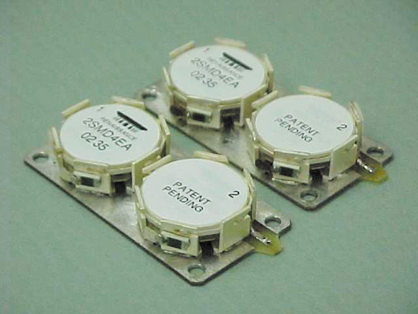
The term surface-mountable usually refers to the electronic components having coplanar ports, so that the unit could be directly mounted on the user's PCB. Another important feature of a truly surface-mountable device is the ability to sustain an aqua-wash after the unit is assembled on a board. The product photograph above shows the basic design of a high power coplanar surface-mount circulator. Coplanarity of ± 0.004" in this new series of ferrite devices was achieved by using a 0.031" thick PCB as a circulator base and by docking all output ports along with the ground on the bottom face of the PCB. The circulator housing is mounted on top of the PCB. The 50 Ω lines and half-moon plated-through holes at the PCB's periphery provide the required transition of contact ports from the top to the bottom face of the PCB. The configuration of all three ports is consistent with standard footprint patterns established in the microwave industry for this class of ferrite devices. The 18 plated-through holes located in the central area carry electrical ground to the housing of the circulator. These via holes become filled with solder when the housing is assembled on a PCB. The completed vias, having a total thermal impedance of 1° to 2°C/W, provide an additional thermal path to the ground. With a typical room temperature insertion loss maintained below 0.25 dB, and less than 0.35 dB over the specified temperature range, the units are rated to 100 W CW forward power. Under forced cooling conditions, the SM devices are capable of handling up to 175 W of CW power. A rigid cap protects the circulator/isolator housing. The cap is made from an epoxy mold and is sealed to the PCB with a silicone rubber adhesive. After assembling on the user's PCB, the unit becomes environmentally sealed and aqua-washable.
The SM circulators and isolators are designed to sustain a temperature rise of 475°F (~245°C) for 10 seconds allowing the utilization of standard reflow procedures during assembly. The usage of a PCB as a base for the ports makes them rigid and inherently coplanar. The SM circulators have a flat top allowing the use of pick-and-place techniques such as vacuum suction or magnetic attraction. The units are also available in tape and reel format.

The two basic models of isolators intended for low power applications, where the reverse power does not exceed 5 W, are shown in Figure 1. The model on the left has the termination attached to the PCB at the location of the third port. The plated-through holes located under the termination provide a thermal path to the bottom sink. This design incorporates the encapsulating cap. An option to this design is the isolator having the termination attached to one of the sidewalls of the housing. This model does not have a cap implying that the unit should not undergo an aqua wash treatment.
The new line of SM isolators includes high power devices that are capable of handling up to 80 W of reverse power. The basic construction is a metal plate with a high power termination attached to the end of the PCB (see Figure 2). The thickness of the metal plate equals the thickness of the user's PCB and it is assumed that the user mounts the PCB on a metal chassis. When the isolator is subjected to a high reverse power, the termination dissipates its heat to the metal plate, which is in thermal contact with the metal chassis. This way the temperature of the termination is maintained under 70°C.

The other SM products include a double-junction isolator developed applying the same conceptual approach as used in the low power units. In double-junction isolators two separate housings share a common PCB, which is shaped to have the contact points complying with the existing standards (see Figure 3 ). The terminations are attached to the sidewalls of the housings. Rated for 100 W of forward CW power, this double-junction circulator allows the dissipation of up to 5 W of reverse power. A similar model, with terminations attached to the metal plate, handles 80 W of reverse power.
Electrical Characteristics
The SM circulators/isolators operate at frequencies ranging from 800 to 2700 MHz. This interval covers the major bandwidths allocated for the cellular market, including AMPS, GSM, DCS, PCS and UMTS bands. The SM circulators are available with the bandwidths varying from 3 to 10 percent depending on the type and model. The standard operating temperature range is specified as -10° to +85°C. However, this range may be extended or shifted according to the specific application requirements. The SM circulators and isolators feature low insertion loss and VSWR, and provide high isolation and excellent thermal stability. Intermodulation distortion (IMD) ranges from -65 dBc with 10 percent bandwidth to -85 dBc with three percent bandwidth. Performance data for various SM series ferrite devices are presented in Table 1.

Mounting Criteria
Heat management is a major issue in high power devices. In applications where the forward power does not exceed 50 W, the SM units can be attached to the user's board using a conducting silver epoxy. At higher power levels, the SM devices should be solder mounted on the board. The surface-mount coplanar design allows standard soldering procedures, including the reflow, to be used to attach the SM devices. In order to ensure proper alignment of the unit on the assembly board, as well as to get the complete encapsulation after the soldering, specific landing patterns are recommended for each of the discussed types of SM devices (available from REC). Unlike other conventional drop-in or surface-mount devices, REC's SM series offers the unique feature of customizing the PCB shape and location of the input and output ports.
Conclusion
This article presents the specific features and technical characteristics of a series of high power surface-mount circulators and isolators. These economically efficient devices combine excellent electrical performance with high volume production capabilities.
The implementation of surface-mount design for circulators and isolators without compromising their electrical performance is accomplished by using a shaped PCB as a support for the housing and the output ports. It is shown that the improvement in IMD performance in "above resonance" circulators is achieved at the expense of the bandwidth. High power isolators capable of withstanding 80 W of reflected power in single- and double-junction configurations in addition to their circulator counterparts are now being offered.
Reference
1. K.N. Kocharyan, "Surface Mountable Low IMD Circulator/Isolator with a Locking Cover and Assembly Method," US Patent No. 6,504,445,2003.
Renaissance Electronics Corp. (REC), Harvard, MA (978) 772-7774, www.rec-usa.com. Circle No. 300