
The Outsized Role of Cable Assemblies
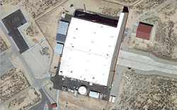
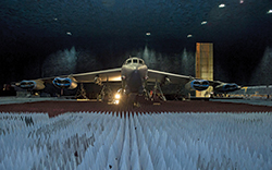
An anechoic chamber creates a free-space environment by suppressing the reflection of electromagnetic energy, achieved by lining the chamber floor, walls and ceiling with electromagnetic absorbent materials. The Benefield anechoic chamber, operated by the U.S. Air Force, is the world’s largest, measuring 264 ft x 250 ft and 70 ft (see Figure 1s)—big enough to house virtually any aircraft (see Figure 2s). The nearly ideal free-space environment is used to test electronic warfare, radar and other electronic systems with defined routines in a controlled environment, simulating actual flight scenarios.
During testing, the aircraft is irradiated with RF energy to stress the EW system to its design limits. The facility’s test equipment transmits signals into the chamber and the aircraft’s EW system monitors and records the data; modern EW systems can independently track and record the system’s responses. Once testing is completed, the facility provides a comprehensive data package to the customer. The data package allows the customer to assess how their system responded to various threat stimuli during the simulation.
In the real world, engagement times are very short, and it is difficult and costly to fly controlled and repeatable scenarios. Assume an engagement where an enemy fighter launches a subsonic air-to-air missile against a friendly fighter. At the time the missile is launched, the two aircraft are four miles apart, converging at a closing speed of 1,200 mph. Optimistically, the friendly EW system has less than 12 seconds to identify the threat, alert the pilot and initiate countermeasures. The effectiveness and reliability of the fighter’s radar, EW and communications systems is clearly crucial to the pilot’s survival.
Asked what system performance problems consistently surface during testing at Benefield, facility personnel answered, “shielding issues with coaxial cables and instrumentation enclosures,” observing that cable assemblies are often damaged during installation. Once compromised, they are susceptible to receiving interference and becoming sources of interference. EW systems gather data from the electromagnetic environment surrounding the aircraft to determine threat types, severity, proximity and location. Poorly shielded cable assemblies or those with damaged shields can “confuse” the EW system, leading to misinterpreted data and extended processing time. EW systems are designed to detect a threat at least 2x the threat’s striking distance; interference can compromise the system’s ability to detect threats at this range.
Benefield staff observed that damage to microwave airframe cable assemblies is usually caused during the installation of the cable or other components near it, not during system use or maintenance. It is not enough that an airframe cable has a good shield design; the cable must withstand the rigors of installation and potential damage when adjacent components are installed in the aircraft.