
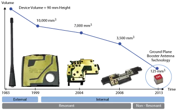
Figure 1 Antenna evolution, from the external single-band antennas to the miniature antenna boosters.
For many decades, antenna and microwave engineering have been adjacent yet fairly separate disciplines. Both have experienced such a high degree of specialization and sophistication that experts in one area would rarely dispute the expertise of someone in the other. While microwave engineers have largely focused on taming the radio waves through all sorts of active (amplifiers, oscillators, active tuners, etc.) and passive (filters, couplers, splitters, etc.) devices, antenna engineers have been exploring new and creative ways to free the waves through increasingly complex fractal-based and related antenna geometries. However this divide may radically change with the introduction of “antenna-less” technology, a technology which makes antenna design much more similar to filter design than to conventional antenna engineering.
Antenna-less technology is based on replacing a complex and usually customized antenna design with an off-the-shelf, standardized, miniature component called antenna booster. Being surface-mount and chip-like in nature, the antenna booster fits seamlessly in an electronic printed circuit board, the same way any other electronic component does, such as a microprocessor, memory, amplifier, filter or switch. It can be assembled with a conventional pick-and-place machine, making the design and manufacture of the next generation of IoT/mobile or wireless devices simpler, faster and more effective.

Figure 2 The CUBE mXTEND™ antenna booster from Fractus Antennas has a volume of 5 mm3.
Miniature chip antennas have been available to antenna and microwave engineers for decades, so what is so radically different about these new antenna boosters that make them worth paying some attention to? The radical innovation is their multiband capability. While conventional miniature chip antennas were based on high-permittivity ceramics and delivered adequate performance for narrowband, single frequency applications (e.g., Bluetooth and GPS), the new antenna-less boosters can deliver full mobile performance within a broad range of frequency bands (e.g., 698 to 2690 MHz) with a single part number. Moreover, their manufacturing is based on conventional low-cost materials (e.g., epoxy-glass substrates or stamped-on-plastics assemblies), making this off-the-shelf solution potentially low-cost at very large production volumes.
An illustration of the radical change that the antenna-less technology means for the design of a new generation of mobile/IoT devices is shown in Figure 1. From the old stubby, external monopole/dipole antennas in early phones to the newest antenna boosters, antenna technology has experienced a tremendous evolution in a race for increasing the number of frequency bands within an always decreasing component size.
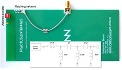
Figure 3 Example of a five band, single-port mobile antenna system based on the CUBE mXTEND™ antenna booster. The evaluation board includes a booster, a ground-plane and a matching network with six components.
Both the challenges of increasing the number of bands and reducing the antenna space have always been met with the mantra that every antenna engineer knows: “one antenna size, one wavelength.” Despite the progress of antenna technology in providing more and more complex shapes to accommodate many bands in a small space, between 2008 and 2012 it seemed that technology had reached a fundamental limit, where antenna size could not be further reduced. After all, the well-known fundamental limit established by Chu and Wheeler in the 1940s states that any device which is much smaller than the operating wavelength (e.g., ≤ λ/10) would radiate poorly or, in the extreme, would not radiate at all. So, how can these tiny antenna boosters that are well beyond the small antenna limit—quite often below 1/30 or 1/50 of the operating wavelength—deliver full radiation performance at mobile frequencies? Moreover, how can they deliver full radiation performance across multiple mobile/wireless wavelengths simultaneously?
THE PHYSICS OF ANTENNA-LESS TECHNOLOGY
A key aspect of antenna-less technology is understanding the importance of combining one or more tiny antenna boosters with a radiating ground-plane. The ground-plane is typically a metallic counterpoise used regularly in just about every electronic wireless device to provide an even zero voltage reference to the device electronics, while introducing some shielding from electromagnetic interference. The ground-plane is used in most mobile and wireless devices as an integral part of a typically unbalanced antenna architecture, namely a monopole or a patch, either as such or in their shorted versions, i.e., the inverted-F antenna (IFA) and the planar inverted-F antenna (PIFA).
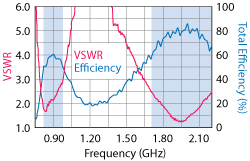
Figure 4 VSWR and antenna efficiency including mismatch losses for the five band, single-port mobile antenna shown in Figure 3.
In these typical antenna architectures, the ground-plane has always made a significant contribution to the overall antenna radiation.1 Now, what the new antenna-less technology is doing is taking that contribution to its limit: the ground-plane becomes the sole radiating element of the system, the booster mainly being a reactive component that balances the ground-plane so that the full RF energy in the form of electric currents is injected strategically onto the radiating conducting layer.
Typically comprising a size comparable to the operating wavelength, the ground layer supports multiple radiating characteristic modes that enable multiple wavelengths to be radiated from the ground layer simultaneously.2 This way, since radiation is obtained from a ground-plane layer that is already in the wireless device, and the antenna element is replaced by a purely reactive element, the wireless device becomes “antenna-less” in the sense of the original radiating antenna having been replaced by a component that induces radiation yet does not radiate, per se.
These new reactive components in antenna-less systems are the so called antenna boosters. An antenna booster is a miniature reactive component, typically smaller than 1/20 or 1/30 of the longest operating wavelength, that can be conveniently embedded into a surface-mount (SMD) component.3,4 Figure 2 offers an example of a commercially available antenna booster. It can take an electric or magnetic form, featuring either a small conductor or a small gap into a conductor, which becomes fed analogously to its conventional electric and magnetic antenna relatives.4 Being so small, these boosters are clearly off-resonance, meaning they need a matching network in order to provide a good match to the RF front-end. By designing the proper matching network, following some microwave engineering matching techniques, multiband radiation performance at virtually any mobile frequency band can be easily obtained from the booster-ground-plane set.
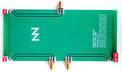
Figure 5 A three-port mobile platform covering the whole set of bands from 698 to 2690 MHz, using four identical antenna boosters.
In many antenna-less systems, it is of upmost importance that both the booster and the matching network components feature a high quality factor (high Q). Since the radiation mainly comes from the ground-plane, the booster becomes a mostly reactive element, which needs to have low losses to prevent draining the RF power before it is conveniently radiated from the ground-plane. Block-solid metallic elements and Faraday cage-like metallic structures are examples of designs that have successfully been used to implement electric boosters,2-4 delivering the same overall efficiency as a much larger customized PIFA or IFA antenna.
One of the key benefits of an antenna-less system is precisely that the frequency response of the overall system is tailored through the matching network rather than through the antenna structure and geometry. With a matching network slightly more complex than that of a conventional PIFA antenna—typically three to seven components rather than the conventional one to three—about any frequency response within the 698 to 2690 MHz frequency range can be tailored from a standardized, SMD antenna component. Consequently, rather than struggling to shape the antenna piece to match the inside of the wireless device and, at the same time, deliver the required radiation performance, the antenna/microwave engineer now needs to focus on designing the right matching network for each particular wireless or mobile device. By skipping the mechanical engineering of the antenna, the design of a wireless/mobile application becomes faster, simpler and more predictable than ever.
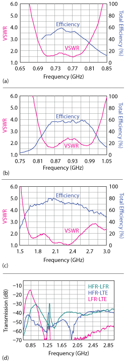
Figure 6 Three-port mobile design efficiency and VSWR for the LTE700 (a), low frequency cellular (b) and high frequency cellular (c) bands. Transmission leakage among the three bands (d).
ANTENNA-LESS 2G, 3G, 4G
The following example illustrates how a mobile platform can be enabled to operate at five frequency bands with a set including a single antenna booster, a matching network and a ground-plane. The booster is 5 mm × 5 mm × 5 mm in size and operates from 824 to 960 MHz and 1710 to 2170 MHz simultaneously. Figure 3 shows the evaluation board, which includes a booster, a ground-plane and a six-component matching network. Note that 5 mm is only λ/72 at 824 MHz, well below the radiansphere of the small antenna limit.5 While the tiny SMD component was installed as any other chip antenna, it actually behaved as a booster by injecting radiation currents on a ground-plane about the size of a typical mobile device such as a smartphone. The actual location of the antenna booster depends on the dimensions of the ground-plane. In this particular example, the corner is the preferred location. The location of the antenna booster with respect to the ground-plane plays an important role in determining the efficiency of the whole radiating system. Once the preferred location is selected, the next step is to provide impedance matching. This two-step process will ensure that the antenna system radiates and receives electromagnetic waves with optimum total efficiency.
As mentioned, because the nature of a ground-plane booster is reactive, a multiband matching network is required to simultaneously match both frequency regions (824 to 960 MHz and 1710 to 2170 MHz). Such a design is not as straightforward as a single band matching network, where an L-type or pi-type circuit is generally sufficient. In this particular case, a matching network of six lumped components was designed. The target criteria for this design procedure was how much power from a generator was delivered to the ground-plane booster, and a microwave computer-aided design (CAD) tool was used for the optimization in accordance with that goal. Once the matching network was designed and integrated in the PCB (shown in the top-left of Figure 3), measurements for VSWR and total efficiency were carried out. The results (see Figure 4) showed a VSWR ≤ 3 across the operating bands and an average total efficiency of 56.7 percent and 75.8 percent in the 824 to 960 MHz and 1710 to 2170 MHz frequency regions, respectively.
Designing through an antenna-less architecture implies a change of paradigm, in which the antenna component (the antenna booster) becomes a fixed part, while the RF system is flexibly adapted to the requirements of each wireless platform or device. For instance, let’s say that the RF architecture requires expanding the range of frequencies to cover the full mobile range of bands from 698 to 2690 MHz while using three separate input ports for the different frequency regions. This markedly different mobile platform can still be designed using the same booster component as shown (see Figure 5). In this test example, four boosters were installed in three corners of the ground-plane using a three to four component matching network6 to interconnect each booster to a coplanar transmission line. The lowest frequency port includes two boosters to increase the overall antenna radiation efficiency including mismatch losses at the most challenging LTE700 frequency band. The test results, shown in Figure 6, illustrate how the system is able to deliver an average antenna efficiency of 46 percent, even at such a low band, rising to an average of 70 percent at the higher one. Isolation is always better than 15 dB in the worst case, staying better than 30 to 65 dB for most of the bands and port combinations.
The example given in Figure 5 illustrates some of the key features of this antenna-less technology: its flexibility and modularity. Nearly any RF architecture can be synthesized using the same off-the-shelf antenna booster building blocks. How would the antenna/microwave engineer need to adapt the above design for use in a mobile/Bluetooth/GPS design with three ports? Again, the same three port architecture and antenna boosters could be used to combine the designs of Figure 5, while changing the matching networks to adapt the system to Bluetooth and GPS.
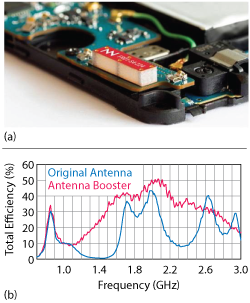
Figure 7 A 12 mm × 3 mm × 2.4 mm antenna booster mounted on a corner of the smartphone PCB (a), enabling a comparison of the overall antenna efficiency of the booster-based antenna with the smartphone’s original PIFA antenna (b).
By choosing the antenna booster as the basic building block of the RF design, a microwave/antenna engineer can imagine an extremely wide variety of architectures, where multiple boosters can be combined to address just about any wireless challenge, from introducing diversity to implementing MIMO7 to developing a robust system which is highly immune to the interaction of the users hand.8
ANTENNA-LESS PERFORMANCE IN A MOBILE PLATFORM
It could be thought that using the ground-plane to support RF radiation currents would make the overall system more sensitive to interference and electromagnetic compatibility (EMC) issues than traditional systems. This is not the case, as systems using conventional PIFA and IFA antennas already use the ground-plane for radiation,1 so booster-based antenna-less systems is no different. This is illustrated by integrating a booster-based antenna in a multiband mobile platform (see Figure 7a). The results of active measurements and field tests were compared with the same measurements of the original embedded customized PIFA antenna (see Figure 7b). In this case, owing to the slim profile of the smartphone used for the demonstration, a slimmer yet elongated booster was used instead of the cubic antenna booster. Measuring 12 mm × 3 mm × 2.4 mm, the booster was retrofitted on a corner of the PCB inside the mobile device, removing the existing laser direct structuring (LDS) antenna.
It is worth noting that the volume of the original antenna is 707 mm3, whereas the volume for the antenna booster is only 86.4 mm3—8x smaller. Despite its much smaller volume, the antenna booster integrated inside the smartphone provides the same efficiency from 800 to 960 MHz, better efficiency from 1710 to 2170 MHz and more balanced efficiency from 2500 to 2590 MHz, as Figure 7b illustrates. Moreover, owing to the larger bandwidth made available by the booster-ground-plane combination, an additional frequency band (LTE2300: 2300 to 2400 MHz) that was not featured in the original smartphone is enabled by the alternative antenna-less solution. Beyond the passive test, a measurement of the total radiated power (TRP) and total isotropic sensitivity (TIS) was conducted as shown in Figure 8. Results showed good alignment with the passive data: similar TRP was obtained at the 850 and 900 MHz bands (LFR) while higher TRP was measured in the 1800 and 1900 MHz bands (HFR). Regarding the TIS, it is worth emphasizing that the measured value was similar for the two cases at LFR and around 1 dB better at HFR.
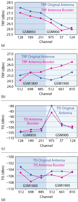
Figure 8 Comparison of the booster-based antenna with the original PIFA antenna: TRP at LFR (a) and HFR (b) and TIS at LFR (c) and HFR (d).
While passive and active parameters (efficiency, TRP and TIS) evaluate the performance from a technical perspective, where testing is carried out in a controlled environment such as an anechoic chamber, field tests generally provide complementary information on how the solution behaves in a real world environment, where multipath fading and interaction with a human operator is present. A fairly simple field test consists of taking the smartphone with the antenna under evaluation and establishing a phone call with another user. Since a field test attempts to reflect performance in a real situation, an urban scenario is usually chosen for conducting the experiment. In general, two kinds of field tests might be carried out: objective and subjective. An objective field test consists of selecting an urban scenario where a user establishes a phone call with the smartphone incorporating the antenna under test and collects the received power from a base station. One of the benefits of this test is that it not only takes into account a real mobile propagation environment with multipath but also the interaction with the user, i.e., both head and hand. The subjective test, in contrast to the objective test, consists of carrying out the same procedure, but instead of collecting data on the received power, the audio quality perceived by the user is considered.
For the objective field test, the following procedure was established. An urban area with several buildings, train tracks and nearby roads was selected. A first user with the antenna under test integrated in the smartphone walked from a starting point to an ending point forming a closed path. The user held the phone in a standard way.9 Then, a second user called the first one to establish a phone call. Using the application GSM Field Test, the received power was collected as a function of the position, while the first user moved at walking speed. The experiment was carried out both for the antenna-less phone and with the original antenna and for two frequency bands: GSM900 and UMTS.
The results, shown in Figure 9, indicate that the received power was, in both cases, stronger at GSM900 than at UMTS, which is consistent with the fact that space losses are higher at UMTS than at GSM (around 7 dB) and also with more power transmitted (3 dB) by GSM900 base stations than UMTS (antenna gains are considered equal). As the results indicate, despite having eight times less volume, the antenna-less solution was able to match or improve the performance of the original conventional antenna in the commercial smartphone. This indicates that not only is the antenna-less system capable of matching the passive performance of a conventional and much larger PIFA antenna, it is also able to deliver adequate performance in real world active wireless or mobile platforms.
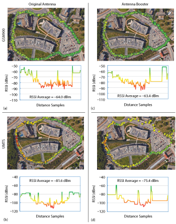
Figure 9 Objective field test results comparing the original PIFA antenna and the antenna-less system: the original antenna operating at GSM900 (a) and UMTS (b) and the antenna booster at GSM900 (c) and UMTS (d).
CONCLUSION
Antenna-less wireless architecture provides a new set of tools and methods for approaching the design of a wireless/mobile device. Antenna and microwave engineering merge in this new technology to deliver a fast, simple and effective design architecture. Owing to the standardization of the antenna part using the new class of miniature SMD antenna boosters, antenna-microwave engineers can design an antenna system via a process that is fast, flexible, modular and very similar to a filter design. No more cumbersome mechanical customization is needed. Additionally, because the booster component is fixed, a potential low-cost solution can be obtained through economies of scale.
The experiments and extensive results show that despite the savings in cost and volume in the device, the performance of an antenna-less system matches that of a conventional one. While the volume of the booster is 8 to 10x smaller than that of an equivalent LDS antenna, the results show that both the passive (radiation efficiency, VSWR, isolation) and active (TIS, TIR) parameters generally deliver comparable or better results for the antenna-less case.
References
- P. Vainikainen, J. Ollikainen, O. Kivekäs and I. Kelander, “Resonator-Based Analysis of the Combination of Mobile Handset Antenna and Chassis,” IEEE Transactions on Antennas and Propagation, Vol. 50, No. 10, October 2002.
- A. Andújar, J. Anguera and C. Puente, “Ground-Plane Boosters as a Compact Antenna Technology for Wireless Handheld Devices,” IEEE Transactions on Antennas and Propagation, Vol. 59, No. 5, May 2011, pp. 1668-1677.
- J. Anguera, A. Andújar and C. Puente, “Wireless Handheld Devices, Radiation Systems and Manufacturing Methods,” Pat. WO 2014/012842 A1, July 16, 2012.
- J. Anguera, A. Andújar, C. Puente and J. Mumbrú, “Antenna-less Wireless Device”, Pat. WO 2010/015365 A2, August 4, 2008.
- H. A. Wheeler, “Fundamental Limitations of Small Antennas,” Proceedings of the I.R.E., 35, December 1947, pp. 1479-1484.
- A. Andújar and J. Anguera, “CUBE mXTEND™ (FR01-S4-250)—A Standard Antenna Solution for Mobile Frequency Bands,” User Manual, Fractus Antennas, June 2017, www.fractusantennas.com/wp-content/uploads/2017/06/UM_FR01-S4-250.pdf.
- J. Anguera, A. Andújar, R. Mateos and S. Kahng, “A 4 x 4 MIMO Multiband Antenna System with Non-Resonant Elements for Smartphone Platforms,” EuCAP Conference, March 23, 2017.
- A. Andújar, J. Anguera and Y. Cobo, “Distributed Systems Robust to Hand Loading based on Non-Resonant Elements,” Microwave and Optical Technology Letters, Vol. 55, No. 10, pp. 2307-2317, October 2013.
- CTIA Test Plan for Wireless Device Over-the-Air Performance, Version 3.6, June 2016.