
Over the air (OTA) measurements will play a vital role in 5G designs, in part because of the introduction of massive MIMO at microwave and millimeter wave (mmWave) frequencies and mobile terminal requirements for multiband and smaller size. The conventional far-field measurement (FFM) method requires large-scale measurement infrastructure and long measurement time. In addition, using FFM in the mmWave band suffers from low measurement accuracy caused by path loss due to the long transmission distance. A proposed near-field measurement (NFM) method solves these problems and helps reduce measurement cost, making it a viable alternative in many applications, including antenna testing.
5G will affect antenna design and characterization in a few, yet significant ways. Current user equipment (UE) designs have several built-in antennas that support various wireless services, and the 5G rollout will most likely result in the antenna count increasing further. OTA testing of the UE will be necessary because implementing a measurement connector for each antenna will increase the size of the UE and raise device cost to impractical levels. Another issue is that 5G base stations will use microwave and mmWave massive MIMO technologies, which will also increase antenna count. The exploding number of antennas makes provision of a measurement connector for each antenna virtually impossible, making OTA testing a requirement.
Figure 1 Antenna field regions.
OTA measurements can be made on the total radiated power (TRP) and total isotropic sensitivity (TIS) of the UE. For massive MIMO, measuring the antenna radiation patterns is a key evaluation item. The basic OTA measurement technique is the 3D integration method using an anechoic chamber. With this approach, the equipment under test (EUT) surroundings are measured as a spheroid form. The problem is that this method requires an anechoic chamber and large-scale measurement equipment. Because FFM is used, the electromagnetic wave loss due to the free-space path loss (FSPL) in the mmWave band is considerable. The result is that there are measurement problems with large error and small dynamic range.
NEAR vs. FAR-FIELD MEASUREMENT
The electromagnetic field radiated from an antenna aperture is divided into regions (see Figure 1). The area near the antenna aperture is called the reactive near-field region, where most of the electromagnetic field components do not contribute to emission. The space where the radiation pattern does not change with distance from the antenna aperture is the radiating far-field region. Generally, this is where the antenna radiation pattern is measured.
The far-field is defined as the distance, R, satisfying the following equation for the maximum diameter, D, of the antenna, where λ is the free space wavelength.
Additionally, the maximum power Wa received by the receive (Rx) antenna in free space is defined by the following equation, where the transmit (Tx) antenna gain is Gt, the Rx antenna gain is Gr, and the Tx power is Wt.
Since R increases for a high gain antenna with a larger aperture, the free-space attenuation increases. The attenuation also increases in the mmWave band because λ is smaller, making measurement of low side lobes difficult.
Figure 2 Planar NFM, showing the relationship between the AUT and scanning area.
The radiating near-field region between the near and far-field areas is where the radiation pattern changes with distance. NFM measures the electromagnetic wave in the near field and calculates the radiation pattern in the far field. The following explains the procedure for finding the radiation pattern.
First, the region near the antenna is examined with a probe antenna connected to a vector network analyzer (VNA) to determine the distribution of the electromagnetic field. Next, the radiation pattern at infinity is found by data processing the amplitude and phase of the captured electromagnetic field. The free-space attenuation is small, because measurements are made close to the antenna.
Compared to FFM, NFM can measure at higher accuracy. There are several types of NFM, depending on the scanning area near the antenna under test (AUT); planar is preferred for antenna measurements because it is suitable for high-gain antennas and has simplified data processing (see Figure 2). With planar NFM, a probe antenna is used to scan and measure the amplitude and phase of the electromagnetic field at a distance of 3λ from the AUT. The distribution of the amplitude and phase at this measurement plane is the Fourier transformation of a function defined by the AUT radiation pattern and the probe antenna radiation pattern. Consequently, this function can be found by reverse Fourier transformation, and the AUT radiation pattern can be found by filtering (i.e., probe correction) the probe antenna radiation pattern from the found function. The radiation pattern is quickly calculated by a computer, because data processing uses the fast Fourier transform (FFT).
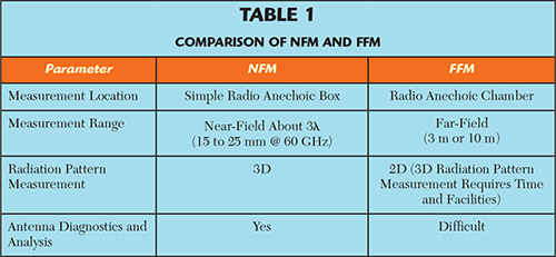
Figure 3 NFM measurement geometry.
The advantages of NFM are shown in Table 1. Since NFM is a close-range measurement method, it does not require use of an anechoic chamber or other large-scale facilities. The mmWave measuring instruments are compact and the radiation pattern can be measured using a simple anechoic box in a room, which eliminates the high cost and extra time necessary to configure a measurement system using a large anechoic chamber. Accurate measurement results are obtained because the method measures a region where the free space loss is small. In addition, NFM captures the entire 3D radiation pattern immediately in front of the AUT, whereas FFM requires many measurements to capture the 2D radiation pattern, i.e., the horizontal (H) and vertical (E) planes. Using FFM to capture the 3D radiation pattern requires a complex measurement setup and a longer measurement time. NFM captures the amplitude and phase distribution near the antenna. If the radiation pattern cannot be acquired, due to the antenna design, the captured amplitude and phase distribution can be used to diagnose the cause. This is a benefit when measuring a phased array antenna, including massive MIMO.
The NFM scanning area is determined by the size of the AUT, the measurement frequency, and the required radiation pattern angular range. The scanning plane, Lx, when the measurement range of the required radiation pattern is θc (see Figure 3) is expressed by the following equation:
Figure 4 E-Band VNA setup for NFM measurement. Not shown in the figure is a 0.8 mm coaxial 145 GHz VNA.
NFM SUCCESS
The probe antenna used for NFM requires three characteristics. First, it must achieve the widest possible beamwidth. Ideally, an isotropic antenna should be used; however, an actual antenna has directivity. Consequently, the probe must be corrected. Probe correction removes the probe antenna radiation pattern from the AUT radiation pattern found by NFM. If a narrow beam antenna is used as the probe antenna, the dynamic range of the radiation pattern is small and causes problems with accurate measurement of low side lobes. Second, the cross-polarization ratio (XPR) must be small, as the AUT radiation pattern is measured for each polarization. Linear polarization antennas are measured by splitting into their vertical and horizontal polarizations, while circular polarization antennas are measured by splitting into the right-hand and left-hand circular polarizations. As the polarization precision of NFM depends on the probe antenna polarization, it is necessary to use a probe antenna with the smallest possible XPR to achieve precision measurements. Lastly, multiple reflections between the probe antenna and AUT must be minimized. This issue can be resolved by using a small probe antenna covered by a radio wave absorber. To minimize the impact of multiple reflections on the measurement, research was done on a measurement method using an optical probe and optoelectronic field conversion.
An open-ended waveguide used as a probe antenna meets the above requirements at mmWave frequencies. Since the aperture plane of this probe antenna is small, the beam is wide, the XPR is about -20 dB and multiple reflections are suppressed by covering the probe antenna with radio wave absorber.
Figure 5 Normalized S21 amplitude and phase measured over 8 hr.
The insertion loss and phase stability of the coaxial cables in an antenna measurement setup deteriorate with frequency, reducing measurement accuracy and making antenna measurements in the mmWave band and higher frequencies difficult. To deal with these challenges, miniature commercial NLTL-based reflectometers have been developed to increase the frequency range of a microwave VNA to 145 GHz (see Figure 4). Essential ingredients in this approach are monolithic NLTL samplers, used so the VNA receivers can cover from 30 to 145 GHz; NLTL harmonic generators, which extend the CW source from 54 to 145 GHz; high directivity directional couplers and a 0.8 mm coaxial port connector. In addition to their miniature size, these reflectometers provide short- and long-term thermal stability (because of the low thermal gradient across the modules), high amplitude and phase stability and raw directivity. Most importantly, placing the sampling directional bridge closer to the AUT measurement signal provides long-term amplitude and phase stability. These features, in particular, lend themselves well to antenna measurements, whether they are performed in a near-field, far-field or compact range scenario. The conduits used to reduce cable complexity provide a framework for extending the length of the cables for far field antenna measurements, when required. By bringing the reflectometers closer to the waveguide probe on one hand and the AUT on the other, mmWave coaxial cable losses are eliminated compared with a traditional measurement setup. Phase and magnitude stability are also improved (see Figure 5).
MASSIVE MIMO ANTENNA MEASUREMENT
A general-purpose antenna commonly has a main beam direction at right angles to the antenna front. Proposed massive MIMO antennas for 5G change the radiation direction by altering the phase of the antenna elements. There are two potential problems when performing NFM using an antenna with such a radiation pattern. First, the near field scanning area is enlarged. When the AUT beam is tilted, locating the radiation pattern of the wide angle matching this tilt requires a wide scanning area. Second, measurement accuracy decreases. FFT calculates the radiation pattern from the near-field distribution. The calculated AUT radiation pattern interval is narrowest near the center (E-plane = 0°, H-plane = 0°), based on a feature of this calculation. Conversely, the interval of the radiation pattern calculation point becomes wider as the angle becomes larger. As a result, the beam is not near the center, so the measurement accuracy may become worse when the beam width is narrow.
Figure 6 NFM system for massive MIMO antennas.
To solve these problems when using NFM to measure a massive MIMO antenna, a measurement system as shown in Figure 6 can be used. The system is composed of an XY positioner, for scanning the near field, and azimuth and elevation tables attached to the AUT. The measurement system can perform measurements even when the AUT beam direction changes. In the case of AUT arrangement, single line scans in the horizontal and vertical planes are performed to obtain the beam direction. From this result, the AUT direction is controlled by the azimuth and elevation tables, and the AUT beam center is matched with the center of the near-field scanning area. With this arrangement, the AUT beam is always at the center of the calculated radiation pattern (E-plane = 0°, H-plane = 0°), which minimizes the measurement area and suppresses any degraded accuracy. If the AUT phase shifter can be operated from the same system, the radiation pattern can be measured automatically while the beam direction changes.
Conclusion
NFM is an effective method for measuring massive MIMO antennas as it reduces free-space losses, yielding measurements with good sensitivity. An NFM system is suitable for OTA measurements in the microwave and mmWave bands — including E-Band — and solves the challenge of measuring massive MIMO antennas. Continual advancement of these systems will help speed development of 5G and mmWave communications systems.