
The Global Positioning System (GPS) was once the only operational global navigation satellite system (GNSS) and it was used all over the world to access location-based services (LBS). With the Russian GLONASS navigation system and the future deployment of China’s Compass and Europe’s Galileo navigation, there will be increased focus on the capabilities and applications of such systems. This article gives an overview of the different navigation systems, explains the navigation channel and generic approach used by a commercial standard receiver to calculate a user position and generally describes channel acquisition and tracking. GNSS applications such as differential GNSS (D GNSS) and multiple frequency-band navigation, their complexity and benefits are also presented.
Global navigation satellite systems are made up of satellites spanning the globe in a set of defined orbits and aim to provide accurate, uninterrupted and global three-dimensional (3D) position and velocity information to users equipped with appropriate receiving equipment. GPS has been operational for some time and GLONASS has just become operational, whereas Galileo and Compass navigation systems will be deployed gradually in the next ten years and may be used in addition to GPS to improve location-based services.
A GNSS network is composed of satellite space vehicles (SV), user equipment (UE) and control stations (CS). Satellite transmissions are referenced to highly accurate atomic clocks onboard the satellites that are synchronous to the GNSS system time base.
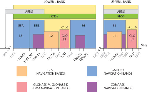
Figure 1 GNSS navigation RF bands.
The worldwide control network monitors the health and status of the satellites and uploads the satellite navigation data, which is composed of immediate ‘ephemeris’ navigation data and non-immediate ‘almanac’ navigation data from different CSs. This data, along with the ranging information tracked at the UE from at least four satellites, enables the receiver module to calculate the satellites’ positions and subsequently the 3D position of the UE.
GPS
The nominal GPS satellite constellation consists of 24 middle earth orbit (MEO) satellites arranged in six orbital planes with four satellites per plane. The satellites broadcast ranging codes and navigation data on three frequencies – L1 (1,575.42 MHz), L2 (1,227.6 MHz) and L5 (1,176.45 MHz) – using code division multiple access (CDMA), as can be seen in Figure 1. Each satellite transmits on these bands, but with different ranging codes than those employed by other satellites. These codes were selected because they have low cross-correlation properties, thereby minimizing the interchannel interference.
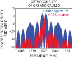
Fig. 2 Power spectral density of GPS L1 C/A and Galileo E1.
GLONASS
GLONASS is a frequency division multiple access (FDMA)-based GNSS. A subcarrier is allocated but not reserved to a specific satellite. GLONASS became fully operational at the end of 2011, when the three nominal orbital planes were completely filled by eight satellites each. All satellites additionally share one spreading code that is optimized for noise suppression. Two satellites can share the same frequency number if they are located at diametrically opposite antipodal points on the same orbit, and therefore cannot be seen by a user on the Earth at the same time. Subcarriers are allocated to GLONASS in the upper and lower bands.
The modernization of GLONASS as part of the GLONASS-K program will be continued. In the future, Russian satellites are to broadcast optimized CDMA signals in the GPS and Galileo L1/E1 bands as well as in other bands, in order to harmonize the GLONASS system with GPS and Galileo.
Galileo
Galileo is an independent European GNSS. It is expected to be partially operational with 18 satellites in 2015 and fully operational with 30 satellites in 2020. One of the benefits of Galileo is that it can complement GPS to provide better navigation performance mainly in urban areas. The system uses CDMA to modulate the satellite signals and thus employs a dedicated spreading code for each space vehicle.
In addition, GPS and Galileo are supposed to share the same frequencies in the upper GNSS band (also called L1/E1) and minimize inter-/intrasystem interference by selecting orthogonal pseudo random noise (PRN) and applying binary offset carrier (BOC) modulation, as shown in Figure 2.
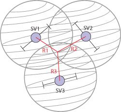
Fig. 3 Illustration of localization using ranging signals from three satellites.
Compass
Compass is a global navigation system that will not be fully operational before 2020. Because the Galileo project has been delayed, China’s regional Compass satellite system Beidou-2, designed to cover large parts of Asia, is scheduled to become operational in 2012 and broadcast on the same bands pre-allocated to Galileo (see Figure 1). These bands can then be acquired solely by the Chinese Compass/Beidou-2 navigation program.
Localization System Model
Navigation employs ranging to determine a user’s position. Therefore, taking ranging measurements from different satellites (which may belong to different navigation satellite systems) makes 3D positioning possible. The geometric range, Ri, is defined as the line of sight (LOS) distance from the satellite to the user. Knowing the position of three satellites and the absolute geometric range at a given UE location from each satellite allows users to locate their position at the intersection of three spheres centered around the satellites, each having a radius, Ri. This basic trilateration approach is illustrated in Figure 3.
The geometric range Ri (equivalent to LOS propagation) is not actually available at the UE, since the satellite signal propagation time gets distorted due to different factors such as refraction in the ionosphere and the troposphere, multipath propagation and satellite clock ambiguities. The distorted version of the geometric range is the pseudorange pi, which is the distance crossed by the ranging signal of a specific satellite to reach a user on the Earth. If ti is defined to be the propagation time of the GNSS signal from svi to the UE, then pi = tic, where c is the speed of light. The ranging observation ti and consequently pi can be directly calculated from the tracked code and carrier phase of the corresponding tracking channel at the UE. The navigation solution based on the aforementioned trilateration concept requires resolving the ambiguity in the pseudorange of every tracked satellite and thereby calculating Ri using the indirectly measured pi and the GNSS satellite-UE channel model that relates Ri to pi.
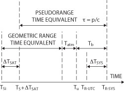
Fig. 4 Illustration of satellite-UE channel model.
GNSS Satellite-UE Channel Model
As shown in Figure 4, the generic channel model that can be used to relate the geometric range to the pseudorange SVi of space vehicle can be expressed as:
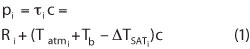
where Tb corresponds to the receiver time bias, Tatm to the atmospheric ambiguities and DTSATi to the satellite clock errors. The geometric range Ri of a satellite (the radius of the trilateration sphere) can be calculated from the observed ti using Equation 1. The UE location is determined by calculating the geometric range of at least four satellites and the corresponding satellite coordinates (xi, yi, zi), which are the centers of the trilateration spheres at Tsi, where

TSYS is the time difference between a specific GNSS system time base and a common system time base for the Universal Time Coordinate (UTC) to be calculated and TR-UTC corresponds to the receiver time in UTC.
Least square algorithms are usually used for UE location and time calculation. Other weighted least square algorithms with weights assigned proportionally to the measured carrier-to-noise ratio (C/N) of every tracked satellite are also very widely used in commercial receivers. Tb, Tatmi and DTSATi are the distortion parameters that differentiate the geometric range from the pseudo range and will be described in the following subsections.
Satellite Position Calculation
To determine the location of the UE, first the position of all satellites must be determined. According to Newton’s laws, the gravitational force exerted by the Earth’s mass M on a satellite of mass m located at a distance r is:
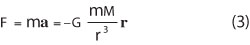
G is the universal gravitational constant; r is the distance between the center of gravity of the Earth and the satellite in an Earth-centered inertial (ECI) orthonormal xyz coordinate system whose x and y axes do not rotate with the Earth. In Equation 3, r = ||r||. The transformation from the differential equation’s ECI coordinate system to the UE coordinate system, which rotates with the Earth and is also called an Earth-centered, Earth-fixed (ECEF) system, is merely a rotation.
Equation 3 should be rotated from ECI to ECEF to obtain a differential equation that can be used to calculate the satellite coordinates in the same UE’s ECEF coordinate system. Only then can the trilateration generic concept work properly.
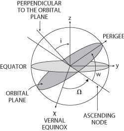
Fig. 5 Satellite's position in ECI.
ECI vs. ECEF
The ECI coordinate system is centered at the Earth’s center of gravity. The xy plane is taken to coincide with the Earth’s equatorial plane. As described in Kaplan1 (section 6), GPS ECI uses the orientation of the equatorial plane at 12:00 UTC on January 1, 2000. The x-axis is fixed in the direction of the vernal equinox (see Figure 5). The z-axis is normal to the xy plane.
ECEF, on the other hand, is the coordinate system used to calculate the position of UE, since it rotates with the Earth. The x-axis points in the direction of 0° longitude. Therefore, the transformation between ECI and ECEF is a rotation of the xy plane. The angle of rotation is derived from the Earth’s sidereal time at any given moment.
Motion equation
The acceleration vector a in Equation 3 is the second derivative of r. Consequently, the two-body mass differential equation of motion in ECI is:
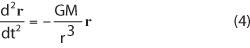
where d2/dt2 is the second derivative operator. The solution to Equation 4 can be shown as an ellipse with its focal point located at the center of gravity of the Earth (see Figure 6). The true anomaly v represents the angle of the satellite in its orbit referenced to the perigee, the orbital point at the shortest distance to the Earth. The semi-major axis of the orbit a and the eccentricity e define the shape of the elliptical orbit and are determined by the location of and the direction in which the satellite is released from its space shuttle.
However, Equation 3 does not describe the motion of the satellite precisely, since ambiguities are caused by the solar and lunar gravitational forces and by the fact that the Earth is not perfectly spherical. This is the reason why GPS and Galileo control stations upload an up-to-date version of the satellite’s Keplerian orbit parameters, e.g., a and e, usually every two hours.
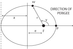
Fig. 6 GNSS orbital parameters.
After locating the satellite in its orbit, the argument of the perigee w, the longitude of the ascending node V and the inclination of the orbit i are used to transform the position of the satellite to ECI using a set of rotations as shown in Figure 6. These parameters are transmitted by GPS and Galileo satellites as part of the ephemeris message.
GLONASS satellites, on the other hand, do not transmit any Keplerian parameters in the ephemeris of the navigation message. They simply transmit the location and the velocity of the satellite at a specific epoch in ECEF.
Rotating the differential Equation 4 from ECI to ECEF and updating it to take into account the spherical harmonics and the gravitational forces of the sun and the moon would allow the UE to estimate the position of the satellite in a time span of 30 minutes around the reference epoch. Fourth-order Runge-Kutta numerical methods are usually used by GLONASS receivers to determine the position of the satellite in a span of 30 minutes based on the motion differential equation and the location and velocity of the satellite in ECEF at the reference epoch. The solar/lunar gravitational accelerations in ECEF are also transmitted as part of the ephemeris of GLONASS satellites.
Applications
Different types of GNSS receivers are used, depending on the precision required by the specific application. To understand these applications, it is important first to understand the generic functionality of the different hardware and software modules of a GNSS receiver. The three basic functionalities of a GNSS receiver are described below.
Acquisition: The receiver uses open loop circuits to search for the Doppler frequency and the approximate code phase for every visible satellite if enough acquisition channels are available in the device. The code phase search window for GPS is 1023 chips, for GLONASS 511 chips and for Galileo 4092 chips. These are the lengths of the corresponding spreading code of the respective GNSS. The search resolution is usually ½-chip, which maps to around 150 m in GPS, since the chip rate of the coarse acquisition (CA) civilian signal is 1.023 MHz.
The search window for the Doppler usually has a resolution of 50 Hz. Signals are acquired on a per-channel basis, and the up to ½-chip phase-ambiguous signal is passed to the code and carrier tracking loops to achieve perfect signal locking, thereby removing code-phase and frequency ambiguities.
Tracking: The code phase acquired from an acquisition channel has a maximum error of ½-chip (150 m in GPS). The code phase is tracked in a delay locked loop (DLL), which utilizes the special correlation properties of GNSS signals to track and lock the code phase. Locking the carrier phase usually happens in a phase locked loop (PLL). The two tracking circuits are interconnected, since the DLL requires that the PLL eliminate the Doppler shift, while the PLL requires that the DLL provide perfect correlation. Like acquisition, signals are also tracked on a per-channel basis. It would not be possible to track a signal without an acquisition stage that initializes the DLL and PLL, thereby allowing them to converge when tracking the GNSS signal of a specific satellite.
Navigation: The navigation algorithm makes use of all the CDMA code-phase and carrier-phase readings (depending on the application) to calculate the position of UE.
Standard GNSS
Standard GNSS receivers usually operate on one frequency band, the L1/E1 band. GLONASS enhances GPS receivers by increasing the probability to find at least four satellites at a LOS. The precision of standard GNSS receivers is around 10 m.
A-GNSS
The calculation of a satellite position requires decoding the navigation message. It takes 30 s in GPS to decode one frame containing an ephemeris set, and the receiver cannot get a position fix before decoding the first three subframes (18 s) of a GPS page. As a result, it takes a long time to get a location fix when booting a GNSS receiver. Using A-GNSS, a mobile communications downlink such as CDMA2000 transmits the ephemeris navigation information to the UE, thereby minimizing the time needed by the UE to get a fix to around 1 s.
Additionally, in the UE-assisted mode of A-GNSS, the mobile phone works as a sensor and thus only acquires and tracks code and carrier phases. An assisted server is responsible for locating the UE on the basis of the reported tracking observations from the UE to a base station (BS). The BS, e.g. LTE BS, transmits some acquisition assistant data to the UE prior to the measurement. This data is used by the UE to reduce its code and carrier phase search windows, thereby minimizing the acquisition effort and consequently accelerating the acquisition process of the GNSS sensor.
The acquisition assistant data is simply the acquired code phase and carrier phase or frequency read from a GNSS receiver located at the BS tower. The UE initializes its acquisition code and frequency search windows around the values transmitted by the BS and in this way reduces the size of the acquisition search windows depending on the maximum BS coverage radius.
Differential GNSS
As expressed in the generic channel Equation 3, two of the most significant factors affecting the accuracy of determining the position of a satellite are the ionosphere and satellite clock correction ambiguities. The vector (baseline) from a static reference point – which is at a close proximity to the user – to the UE can be determined by simply processing the tracking readings or the ionosphere delay as well as the satellite clock error of the static reference point at the UE. This makes it possible to eliminate the similar ambiguities in the ionosphere and satellite clock and thus improve the performance of GNSS to 1 m. The transmitted correction data is called differential data. GNSS performance can increase even more if carrier phase readings are additionally used.
Differential corrections are usually transmitted using regional navigation satellite systems, which are also called satellite-based augmentation systems (SBAS). The best known SBAS is the American WAAS providing D-GPS service to North America.
Multiple Frequency GNSS
Satellites sometimes transmit the same signal on different bands, e.g., GPS on L1 and L2. By combining tracking readings from L1 and L2, it is possible to remove the ionosphere ambiguities. This is because the ionosphere deflection from the LOS is inversely proportional to the square of the carrier frequency. As a result, GNSS performance can be improved to the range of 5 m.
Conclusion

Although many advanced applications such as multiple frequency GNSS and differential GNSS can improve the performance of GNSS receivers significantly, the commercial solutions are still heavily limited to standard GNSS and A-GNSS because they are easy to implement. In the future, the market trend will continue to move toward combining GNSS signals on common bands such as L1/E1 to increase satellite availability in urban areas.
Reference
1. E. Kaplan and C. Hegarty, Understanding GPS: Principles and Applications, Artech House, 2006.
Rachid El Assir received his bachelor’s degree in electrical engineering from the American University of Beirut in 2003 and his master’s of science degree in communications engineering from Munich Institute of Technology in 2005. Since then he has been working on the baseband development of Rohde & Schwarz state of the art signal generators. El Assir currently leads the development of the global navigation satellite systems (GNSS) program on vector signal generators.