
The design for the Vivaldi antenna is motivated by the need for a broadband measurement antenna for an antenna test range (ATR). The ATR is capable of a dual axis rotation to create 3-D plots and to calculate the total radiated power (TRP).1 The TRP calculation involves the summation of the measured radiated power due to Eφ and Eθ. Therefore, measurement of each polarization is required.
Because of the need for quick characterization of antennas in the ATR, it is desirable to have a receiving antenna that can be electronically switched to receive Eφ or Eθ. Otherwise, the antenna under test (AUT) would need to be rotated for each polarization, making the test twice as long.
Currently, dual polarized dipoles are used to achieve fast characterization. Cross-polarization isolation in excess of 20 dB can be achieved with these dual dipoles. However, as the frequency gets higher (a few gigahertz), the dipoles become more tedious to construct due to their small size. Also, since the dipoles are inherently narrow band, it is quite desirable to replace them with a broadband dual polarized antenna. The Vivaldi (end fire exponentially tapered slot) antenna array is a promising candidate for this application since it has been shown to exhibit the desired characteristics: a broadband pattern, broadband impedance and high cross-polarization isolation.2,3
The Vivaldi Element
The operation of the Vivaldi antenna itself is not yet fully understood.4 Interested readers are referred to the book by Lee and Chen,4 which provides an overview of the tapered slot antenna (TSA) and its many variations. For the purpose of this article, only a qualitative description of the traveling wave mode Vivaldi antenna is attempted.
Briefly, the traveling wave mode Vivaldi antenna provides a smooth transition between the guided wave traveling in the slot transmission line (slotline) and the plane wave, which is radiated.4 This transition is achieved by a gradual tapering of the slotline. Since the slotline is a balanced transmission line, a wideband balun is an important component in the antenna design. A description of a printed Vivaldi with a microstrip feed is provided in Figure 1. The microstrip line is printed on a substrate and the tapered slotline is etched on the ground plane below the microstrip.

Fig. 1 Schematic of a Vivaldi antenna.
A few parameters are considered to be of great importance for satisfactory wideband performance:
• The length and the width of the tapered slotline: to achieve the traveling wave mode of radiation, the slotline length and width generally needs to be greater than λo and λo/2, respectively.4
• The opening rate of the tapered slotline: the Vivaldi antenna employs an exponential taper.4 The coordinates of the tapered slot are defined by3:
![]()
where


The points (x1,z1) and (x2,z2) are the end points of the flare and R is the variable that changes the rate of the opening. The performance of the antenna is very dependent on R.
• The dimensions of the microstrip-to-slotline (M-S) transition: To achieve a broadband transition, the microstrip open stub and the slotline short stub are to present a virtual short and a virtual open at the point of transition, respectively. To that end, the radius of the radial microstrip stub (Rrad) and the diameter of the circular slot stub (Ds) may be approximated by λm/4 and λs/4, respectively. The λm is the effective wavelength of the microstrip and ls is the effective wavelength in the slotline. In-depth discussions on the M-S transitions are given in references 5,6,7.
The Dual Polarized Array
To achieve the dual polarization, two coplanar horizontal and two coplanar vertical Vivaldi elements are arranged into an array. The pair of active co-polarized elements is driven with equal phase and equal amplitude excitation to achieve a broadside pattern. The cross-polarized elements are switched off using an electronic switch.
The arrangement of the array is such that it is symmetric around its axis, as shown in Figure 2. A few advantages are expected from this arrangement. First, the phase center of the array will be on the array’s axis regardless of which pair is active. Second, due to symmetry and the broadside excitation, the effect of the active pair on the cross-polarized pair is expected to cancel. Of course, the cancellation will not be perfect because of the inherent asymmetry in the Vivaldi elements since a microstrip feed is used. Better symmetry in this regard may be accomplished by using a stripline feed.3 However, this approach is not attempted here because of manufacturing limitations. Cross coupling between the co-polarized elements exists; however, it is predicted that the gap between the elements will minimize this effect.

Fig. 2 Broadside view of a Vivaldi antenna array.
Design Goals and Procedure
The goals for this design are as follows:
- VSWR less than 2 from 3.4 to 6 GHz.
- Broadside pattern with gain greater than 4 dBi from 3.4 to 6 GHz.
- Broadside cross-polarization isolation greater than 10 dB from 3.4 to 6 GHz.
- From experience, it is felt that the following iterations yield a reasonably good design in an efficient manner:
- Determine the antenna width based on the array’s spacing requirement: For a broadside array, the element spacing (d) must be less than λo at the highest frequency to avoid grating lobes.
- Determine the antenna length and width based on the traveling wave design requirements: Recall that the slotline length and width generally needs to be greater than λo and λo/2 at the lowest frequency, respectively.
- Select a board material: A treatment of the effect of the dielectric on the performance of the Vivaldi antenna is given in Kasturi, et al.8
- Design the microstrip-to-slotline transition for the required frequency range with S11 less than –15 dB. The characteristic impedance Zo of the slotline and the port impedance may be varied for best S11.
- Connect the M-S transition to the tapered slotline: Vary the opening rate until the VSWR, gain and cross-polarization specifications are met. Re-optimize the M-S transition if necessary.
- Design a microstrip tapered line to match the Zo of the microstrip to 50 Ω.
- Ensure that the coaxial connector to the microstrip transition is acceptable.
- Arrange the elements in the dual polarized array and verify that the VSWR, gain and polarization goals are met. Re-optimize if necessary.
Design Process and Simulation Results
Following the design procedure, the following dimensions were determined:
- Array spacing, d = 1 • 30 cm/6 GHz = 5 cm.
- Flared slotline length, fl = 30 cm/ 3.4 GHz = 8.8 cm.
- Flared slotline width, fw = 0.5 • 30 cm/3.4 GHz = 4.4 cm. However, due to the d requirement and the need for spacing between the antenna edges, the antenna width (aw) was set at 4 cm. The fw was set at 3.6 cm such that the ends of the taper are 0.2 cm away from the top and bottom edges of the board. Therefore, the spacing between the co-polarized elements is 1 cm.
- A Rogers RO4003C™ (?r = 3.38, tan ? = 0.0027) board, 60-mil thick, was selected.
Next, the M-S transition was designed on a RO4003C™ board based on the information gleaned from the literature.5,6,7 A pair of M-S transitions was simulated in HFSS and the results were found to be satisfactory.
Figure 3 shows the configuration of a pair of M-S transitions. The dimensions were as follows: Ds = 1 cm, Rrad = 0.8 cm (90° radial stub), slotline gap (Sg) = 0.1 cm. The result of the simulation shows that the S11 of the pair of the M-S transition is below –14 dB in the 3.4 to 6 GHz range, as shown in Figure 4.
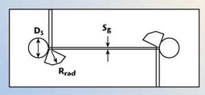
Fig. 3 A pair of M-S transitions.

Fig. 4 Return loss of a pair of M-S transitions.
The next step was to integrate the M-S transition with the tapered slot. The opening rate R was varied until the VSWR was found to be less than 2 in the frequency range of interest. The gain and cross-polarization isolation were then verified at a few frequency points. It was decided that R = 2 is the optimum opening rate. The effect of R on the antenna VSWR is shown in Figure 5. A properly tapered microstrip line was designed for a 50 Ω nominal input impedance. The resulting Vivaldi element is shown in Figure 6. The simulated radiated performance of the Vivaldi element is summarized in Table 1. The H-plane pattern at 4.5 GHz is shown in Figure 7.

Fig. 5 Dependence of a single Vivaldi antenna VSWR upon R.

Fig. 6 Single Vivaldi antenna element.


Fig. 7 H-plane element pattern at 4.5 GHz.
Since the performance of a single element meets the design goals, the next step is to simulate the dual polarized array. The elements were arranged as described previously with 1 cm of spacing between the co-polarized elements. The two-port S-parameters were measured and the gain patterns were calculated when a pair of co-polarized elements was driven with equal amplitude and phase excitation. The simulated radiated array performance is summarized in Table 2. The H-plane pattern of the array at 4.5 GHz is shown in Figure 8.


Fig. 8 H-plane array pattern at 4.5 GHz.
It is noted from the data that the cross-polarization isolation gets worse at the lower and upper frequencies. Also, at the lower frequency, the pattern appears to be less symmetric. A hypothesis regarding the rise of the cross-polarized components and the pattern asymmetry is that they are due to the coupling between the microstrip feeds.
The SMA connector was also simulated in HFSS and connected to the input port of a single element Vivaldi antenna. It was observed that the coaxial-to-microstrip transition did not introduce a significant change to the antenna impedance for this design.
Antenna Array Fabrication
A board layout was generated and the antenna boards were manufactured using the RO4003C material. The tapered slot and the microstrip feed were etched using a milling machine at the University of Calgary. The elements were then arranged into an array by placing them on four plastic clips which were glued onto each side of a 3/8 inch wood dowel, as shown in Figure 9.

Fig. 9 The assembled Vivaldi antenna array.
Measurement Setup and Results
Initially, the S11 of a single Vivaldi antenna was measured using a network analyzer (NWA). The measured S11 was compared to the HFSS simulated S11 of a single element. Figure 10 shows the comparison between simulated and measured S11.

Fig. 10 Measured and simulated return loss of a single Vivaldi antenna element.
The antenna array was measured at the University of Calgary anechoic chamber. The coplanar active elements were connected together via a two-way isolated power divider (MA/COM 2090-6204-00). The cross-polarized elements were left unterminated. A diagram of the arrangement is shown in Figure 11.

Fig. 11 Radiated measurement setup for co-polarization gain and pattern.
For gain measurement, a conical log-spiral antenna (EMCO Model 3102) with a known gain was used as a calibration antenna for the measurement setup. Also, the losses in the cables that connect the divider to the elements were accounted for in the gain calibration. The array was rotated on the base of the turntable to measure the H-plane pattern. To measure the cross-polarization isolation, the horn RX antenna was rotated 90° and the turntable rotation was repeated. For the E-plane pattern, the array was rotated by 90° by turning the wood dowel.
The measured results are summarized in Figures 12–20. A filter function in Matlab was used with a window of five data points for gain vs. frequency, combined S11 vs. frequency and cross-polarization isolation vs. frequency plots.

Fig. 12 Return loss of the combined Vivaldi antennas.
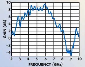
Fig. 13 Broadside gain of the combined Vivaldi antennas.

Fig. 14 Broadside cross-polarization of the combined Vivaldi antennas.

Fig. 15 Co-polarized pattern of the combined Vivaldi antennas at 3.4 GHz.

Fig. 16 Cross-polarized pattern of the combined Vivaldi antennas at 3.4 GHz.

Fig. 17 Co-polarized pattern of the combined Vivaldi antennas at 4.5 GHz.

Fig. 18 Cross-polarized pattern of the combined Vivaldi antennas at 4.5 GHz.

Fig. 19 Co-polarized pattern of the combined Vivaldi antennas at 6.0 GHz.

Fig. 20 Cross-polarized pattern of the combined Vivaldi antennas at 6.0 GHz.
Conclusion
A dual polarized Vivaldi array has been designed that meets all the design goals. The measurement results show that VSWR is < 2 from 3.4 to 6 GHz, the broadside pattern shows a gain > 4 dBi from 3.4 to 6 GHz and the broadside cross-polarization isolation is > 10 dB from 3.4 to 6 GHz. Also, the design iteration for a four-element, microstrip-fed, dual polarized Vivaldi array has been suggested. It is hoped that this proposed design iteration would aid the design of similar antennas.
Acknowledgments
This work was done as part of a University of Calgary graduate course in antennas. The authors would like to thank Dr. Michal Okoniewski for allowing the use of the university’s anechoic chamber and Mr. John Shelley for manufacturing the Vivaldi elements. The authors also thank Murandi Communications Ltd. for the use of the simulation software.
References
- Murandi Communications Ltd. homepage (www.murandi.com).
- S. Balling, M. Hennhofer, G. Sommerkorn and R. Stephan, “Wideband Vivaldi Arrays for Large Aperture Antennas,” 48. Internationales Wissenschafliches Kolloquium, Technische Universitat Ilmenau, September 2003.
- D.H. Schaubert and T.H. Chio, “Wideband Vivaldi Arrays for Large Aperture Antennas,” Perspective on Radio Astronomy – Technologies for Large Antenna Arrays, Proceedings of Conference at the ASTRON Institute, April 1999, pp. 49–57.
- K.F. Lee and W. Chen, Advances in Microstrip and Printed Antennas, John Wiley & Sons Inc., Somerset, NJ, 1997, Chapter 9, “Tapered Slot Antenna” by R.Q. Lee and R.N. Simons.
- M.M. Zinieris, R. Sloan and L.E. Davis, “A Broadband Microstrip-to-Slotline Transition,” Microwave and Optical Technology Letters, Vol. 18, No. 5, August 5, 1998, pp. 339–342.
- B. Schuppert, “Microstrip/Slotline Transitions: Modeling and Experimental Investigation,” IEEE Transactions on Microwave Theory and Techniques, Vol. 36, No. 8, August 1998, pp. 1272–1282.
- K.C. Gupta, R. Garg, I. Bahl and P. Bhartia, Microstrip Lines and Slotlines, Artech House Inc., Norwood, MA, March 1996.
- S. Kasturi, A.O. Boryssenko and D.H. Schaubert, “Infinite Arrays of Tapered Slot Antennas with and without Dielectric Substrate,” IEEE Proceedings of the Antenna Application Symposium 2002, Monticello, IL, pp. 372–390.