

Any time that multiple RF systems are co-located, there is an opportunity for RF interference (RFI) to degrade or disrupt the performance of receivers. The impact of RFI includes decreased performance, delayed product releases, product recalls and safety-critical scenarios. RFI is a very serious matter that must be addressed throughout the design of products and systems.
RF Requirements vs. Compatibility
Individual RF units must meet performance standards that specify limits for both in-band and out-of-band operation. Meeting the individual unit level tests can sometimes incorrectly lead you to believe that RFI problems will not occur when multiple RF systems are integrated. This is not true.
Commercial and military requirements do not ensure compatibility. For example, MIL-STD-461 includes a thorough explanation about not being able to address every possible scenario in which the RF systems will be used. Therefore, meeting MIL-STD-461 at the unit level does not ensure compatibility for every combination of RF equipment, antennas, and external components (e.g., filters, amplifiers, etc.). It is up to you to ensure that your product or system will not experience or cause RFI.
A combination of simulation and testing is necessary to identify RFI problems early and then develop optimal solutions to mitigate the problems. The Ansys EMIT technology was developed specifically for the RFI problem. It employs a multi-fidelity approach that allows users to incorporate both high-fidelity data and parametric models. This is an extremely important capability, as engineers almost never have high-fidelity data for all components and coupling mechanisms at the beginning of the analysis.
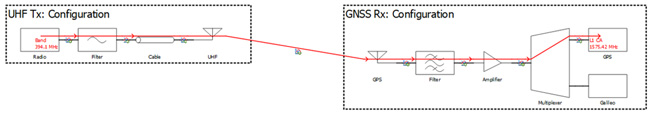
The image below shows a block diagram for an interference problem between a UHF transmitter and a GNSS receiver. There are components between the radios and the antennas such as filters, cables, amplifiers, and multiplexers. Many component vendors now provide measured S-parameters on their website. Here is an example for a bandpass filter from Mini-Circuits where the user can download the S-parameters. One also needs the antenna-to-antenna coupling. The Ansys HFSS product provides users with multiple solver technologies spanning electrically small to very electrically large problems. Using these tools, one can simulate the broadband antenna-to-antenna coupling.
What is not readily available is broadband data for the transmitter emissions and the receiver susceptibility. One approach is to use vendor specification sheets for commercial systems or DD 1494s for military systems to develop parametric models for the transmitters and receivers. However, spec sheets and DD 1494s do not include the detailed information necessary for an accurate RFI analysis. For example, analysts need to know the harmonics and the spurious emissions for a transmitter. Most spec sheets and DD 1494s provide very limited information on the harmonic amplitudes, such as a not-to-exceed threshold or information only on the 2nd and 3rd harmonics. Further, it is common that a single not-to-exceed value is provided for spurious emissions. This type of information is not very useful.
For receivers, selectivity information describing the in-band response of the receiver is sometimes provided and, potentially, the local oscillator (LO) and intermediate frequency (IF) data. Using this data, you can compute unintended responses of the receiver where an RF signal can mix with the LO to yield a frequency that passes through the IF filter. However, this only indicates the potential for the receiver to be susceptible at such frequencies.
Limited Data Can Limit RFI Analysis
There are two major problems with using spec sheet or DD 1494 data to build your transmitter and receiver models. First, given the limited and conservative nature of the data provided from these sources, the RFI simulations often predict many false interference problems. The second problem is that models built from spec sheets and DD 1494s lack important features, and as a result, real interference problems are missed.
Consider the figure below where we show a comparison between a model built for a UHF transmitter using spec sheet information and measured data collected with EMA’s ARMS. The spec sheet accurately captures the amplitude of the 2nd and 3rd harmonics of the transmitter, but the amplitudes for subsequent harmonics are up to 50 dB higher than the actual measured harmonics. Using the spec sheet harmonic amplitudes can result in predicting interference problems that do not exist. Further, the spec sheet provided no information on the spurious emission limit for this transmitter and there are clearly many significant spurious emissions.

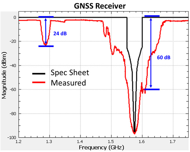
We must also consider the receiver’s performance. In the image below, we show a comparison between spec sheet data and measured data for a GNSS receiver tuned to L1. There are several features that stand out in this image. First, the measured selectivity of the receiver is much broader than the spec sheet selectivity. In places, the spec sheet model is off by as much as 60 dB! Second, there is an out-of-band response near 1280 MHz. This is not the L2 response of the receiver but rather a spurious response of the receiver.
To further illustrate the importance of measured data in RFI simulations, consider a UHF transmitter operating at 390 MHz and a GNSS receiver operating at L1 (1575.42 MHz). There is no obvious interference between these two systems. The 4th harmonic of the UHF transmitter occurs at 1560 MHz. While this is relatively close to the L1 frequency, the selectivity specified on the GNSS receiver spec sheet indicates that there should be no interference. An EMIT simulation shows that the 4th harmonic of the UHF transmitter is 10 dB below the susceptibility of the receiver at 1560 MHz. However, when we use measured data in the EMIT simulation, we predict an interference problem with a magnitude of 35.6 dB! The spec sheet model was off by almost 46 dB.

Electro Magnetic Applications (EMA) performs RFI analysis for many customers for several types of platforms including aircraft, ground vehicles, ships, satellites, and rockets. By using ARMS measured data for transmitters and receivers with Ansys technologies, EMA has been able to identify many interference problems for our customers that would have otherwise been missed until final testing or after the system had been fielded. Contact EMA to learn how you can use this workflow to support your products. Watch how you can predict Radio Frequency Interference with Ansys EMIT technology in this free on-demand webinar here.