

Recently, more attention has been paid to applications of ultrawideband (UWB) technology on wireless communication. It offers advantages of decreased cost and increased capabilities, compared with other conventional radio technologies. Standards activities for UWB systems are promoting a global perspective for not only technology but also regulations. UWB has the characteristics of low cost, bulk data transmission rate and very low power consumption that make it attractive in local area networks, position location and tracking, and radar systems. Planar bandpass filters, with a wide bandwidth of 3.1 to 10.6 GHz, are highly suitable for integration of UWB front-ends. A planar bandpass filter, based on a microstrip structure, can provide the advantages of easy design, lower fabrication cost and compact size, and has been widely used. In addition, a dual-mode resonator is often built into the microstrip related bandpass filter design to improve the passband and rejection. Planar dual-mode filters have been introduced, which offered significant size, weight and cost advantages over cavity and dielectric resonator designs.1 Several authors, dealing with the advances of novel materials and fabrication technologies,2–5 have discussed the filtering characteristics of different configurations. These types of filters were ideally suited for narrow bands. A new generation of microwave dual-mode filters, using square ring resonators with enhanced L-shaped coupling arms, was later discussed.6 Advantages of low insertion loss, sharp rejection band and wide passband were obtained. Subsequently, the area of the overall filter structure was reduced and a sharper passband was provided. However, the presence of spurious harmonics was a fundamental drawback.7 A number of improved structures, such as an I/O taping line, defected ground structure (DGS), split ring resonator (SRR) and photonic band-gap (PBG), have proven to be effective in suppressing spurious harmonics. These techniques either increase the complexity of fabrication or enlarge the component’s size. It has been proven that a filter, incorporating two spur-lines at the input and output feed lines of the coupled ring, can increase the rejection band of the bandpass filter.8 The ideas demonstrated in this article are to implement spur-line structures in the square ring resonator to suppress the spurious harmonics without altering the passband response of the filter.
Dual-mode, Wideband Microstrip Bandpass Filter
A novel bandpass microstrip filter, based on a ring resonator, is shown in Figure 1. The input and output ports are directly connected to the ring resonator at 180° and 270°. Two stepped-impedance tuning stubs are implemented within the resonator at 0° and 90°, and a 0.5 by 0.5 mm perturbation is positioned at 45°. The circumference lr of the ring resonator is given by Equation 1, where n is the mode number and ?g is the guided wavelength
![]()
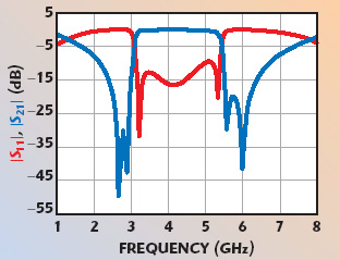
The ring resonator and the ?/8 stepped-impedance stubs are designed for a resonance frequency of 4.2 GHz and fabricated on an RT/duroid 6010.2 substrate with a thickness h = 25 mil and a relative dielectric constant ?r = 10.2. The dimensions of the filter are l = 7.4 mm, m = 3.55 mm, n = 0.7 mm, t = 2.6 mm, w = 0.6 mm and p = 0.5 mm. The simulated results of the filter are shown in Figure 2. The perturbation stubs can generate two transmission zeros, or dual modes, on either side of the passband within the 2.68 to 2.87 and 5.56 to 5.99 GHz bands. The filter has a 3 dB fractional bandwidth greater than 56 percent and an insertion loss better than 0.3 dB.
Spur-line Bandstop Filter Configuration

Figure 3 shows the configuration of the spur-line filter. The parameters k and g, the length of the spur and the gap, determine the resonant frequency of the spur-line bandstop filter. Based on the analysis introduced by Nguyen and Hsieh,9 a spur-line bandstop filter on a homogeneous medium can support two quasi-TEM modes, that is an even and odd mode, and each mode propagates with a different phase velocity. The equivalent circuit model in matrix form can be constructed through manipulations of the impedance matrix of parallel-coupled transmission lines and termination conditions. It is proven that the filter type, either bandstop or bandpass, is mainly dominated by the odd mode of propagation, and the computations for the two parameters k and g are related by the effect of the odd mode fringing capacitances. The length of the spur-line is given by8


where the center frequency of the designed filter is f0 and Keffo is the odd mode effective dielectric constant. The modifying term ?k is an effective length resulting from the effect of the gap g. In this case, k and g are 3.4 and 0.2 mm. This designed spur-line filter was embedded in the input and output microstrip lines of the ring resonator, as shown in Figure 4. A new ultrawideband microstrip bandpass filter, based on a dual-mode ring resonator with spur-line structures placed at input and output ports, is created.
Measurements
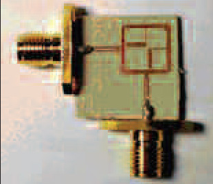
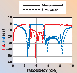
The overall size of the filter is 15.7 by 15.7 mm, and the prototype filter is shown in Figure 5. The passband and stopband responses of the designed bandpass filter are shown in Figure 6. The perturbation stubs can generate two transmission zeros or dual modes on either side of the passband within 2.70 to 2.89 GHz and 5.65 to 5.73 GHz. The filter has a 3 dB fractional bandwidth of 57 percent, an insertion loss better than 0.8 dB and a return loss greater than 10 dB in the passband from 3.1 to 5.6 GHz. The spurious response of the designed filter is effectively suppressed. The rejection of the spurious response from 5.8 to 8.5 GHz is successfully suppressed to a level lower than –20 dB through the effect of the input and output spur-lines.
Conclusion
The design for a UWB bandpass filter with spurious response suppression is proposed and shown in this article. Its characteristics are compact size, sharp rejection, low insertion loss and wide stopbands. The measured performance shows good agreement with the simulated results. The slight difference between the simulated and measured results may be due to a fabrication error, which can be improved by more precise fabrication technology. With the addition of the spur-line structures, another transmission zero can be created to suppress the spurious response without changing the prototype design. In addition, the maximum attenuation in the stopband of the proposed filter is more than 33 dB without degrading the performance of the bandpass filter. Specifically, the resonance frequency of the spur-line bandstop filter can be accurately and conveniently calculated. These features make spur-line bandstop filters more attractive in modern communication applications.
References
1. J.A. Curtis and S.J. Fiedziuszko, “Miniature Dual-mode Microstrip Filters,” 1991 IEEE MTT-S International Microwave Symposium Digest, Vol. 2, pp. 443–446.
2. J.S. Hong and M.J. Lancaster, “Bandpass Characteristics of New Dual-mode Microstrip Square Loop Resonators,” Electronics Letters, Vol. 31, No. 11, May 1995, pp. 891–892.
3. J.S. Hong and M.J. Lancaster, “Microstrip Bandpass Filter Using Degenerate Modes of a Novel Meander Loop Resonator,” IEEE Microwave and Guided Wave Letters, Vol. 5, November 1995, pp. 371–372.
4. L.H. Hsieh and K. Chang, “Dual-mode Quasi-elliptic-function Bandpass Filters Using Ring Resonator with Enhanced Coupling Tuning Stubs,” IEEE Transactions on Microwave Theory and Techniques, Vol. 50, No. 5, May 2002, pp. 1340–1345.
5. L. Zhu, P. Wecowski and K. Wu, “New Planar Dual-mode Filter Using Cross-slotted Patch Resonator for Simultaneous Size and Loss Reduction,” IEEE Transactions on Microwave Theory and Techniques, Vol. 47, No. 5, May 1999, pp. 650–654.
6. L.H. Hsieh and K. Chang, “Compact, Low Insertion Loss, Sharp Rejection and Wideband Microstrip Bandpass Filters,” IEEE Transactions on Microwave Theory and Techniques, Vol. 51, No. 4, April 2003, pp. 1241–1246.
7. C.Y. Chen, C.Y. Hsu and S.F. Lin, “A Novel Compact Miniaturized Wideband Microstrip Bandpass Filters with Dual-mode Ring Resonators,” Microwave and Optical Technology Letters, Vol. 45, No. 4, May 2005, pp. 312–315.
8. U. Karacaoglu, D. Sanchez-Hernandez, I.D. Roverson and M. Guglielmi, “Harmonic Suppression in Microstrip Dual-mode Ring Resonators Bandpass Filter,” 1996 IEEE MTT-S International Microwave Symposium Digest, Vol. 3, pp. 1635–1638.
9. C. Nguyen, C. Hsieh and D.W. Ball, “Millimeter-wave Printed Circuit Spur-line Filters,” 1983 IEEE MTT-S International Microwave Symposium Digest, pp. 98–100.