
Multipath, shadowing and fading effects are major challenges in the reliable operation of terrestrial wireless communication channels. Signals from transmitter to receiver bounce from various objects and from the ground, and add in the receiver antenna in a way that can be destructive to signal strength and therefore to communication quality and throughput. In addition, effects like shadowing, scattering and diffraction add to the complexity of the propagation in the channel. These effects have been a major concern in the design of various wireless networks and cellular standards (GSM, CDMA, 802.11, etc.). Overall signal reliability is especially acute in the design of miniature sensor radio systems, with their ultra limited power sources (small batteries) and operation in highly fading channels, when running close to ground level, in medical facilities, buildings, or even in-vivo.
The principle of space diversity uses multiple antennas (at least two), distributed in space with their signals processed, either independently or in concert. The “redundancy” built into such systems improves significantly both reception quality and reliability.
Of the various techniques available to combat multipath (spread spectrum has been heavily utilized in the last 10 years, either direct sequence, CDMA, or frequency hop configurations, 802.11), antenna directivity and diversity is the most powerful but also the most complicated and least economical, because of the extra hardware (and power) associated with the use of more than a single antenna. This technology, which has been used mainly in large installations, such as cellular base stations, is now emerging as a viable economical solution even in handheld devices. Array processing was previously complex and expensive, but with the advent of simpler processing algorithms, low power integrated radio ASICs and exponentially growing DSP engines, the limitations are gradually being mitigated.
Space diversity requires a certain “spatial separation” between the distributed elements, otherwise their signal will be correlated and the application offers no advantage. However, diversity can also be in polarization (left hand/right hand circular or vertical/horizontal, for example), which allows proximity between elements. Generally, cross-correlation below 0.5 is required. Since that separation is in the order of ?/3 to ?/2 (for vertical or horizontal polarization), physical separation in handheld devices at higher frequency platforms is very realistic. It is therefore possible in cell phones, WLAN terminals and in miniature network sensors operating at the higher ISM bands.
This article has been written from the standpoint of miniature (< 1 cubic inch, including the battery) radio-sensor technology, which is also only now emerging. It highlights briefly the alternatives, the modeling and the processing of miniature antennas, and reviews miniature antenna diversity and combining techniques.
Equations will be introduced for miniature antenna parameter calculations, performance limits will be reviewed and the focus will be on the performance of various small antennas and the advantages of antenna array processing, specifically antenna combining. The terminology and terms will be highlighted. Some simulation results will be provided, and technological and business opportunities and challenges will be pointed out.
Terrestrial wireless communications suffer from multipath, shadowing and fading effects. The electro-magnetic signals, which usually have a direct path from transmitter to receiver antenna, are also accompanied by other signals being reflected from the ground and from various objects in the neighborhood. These signals (hence multipath), or vectors, add in the receiver, mostly canceling and causing the deteriorating effects of channel fading.
The transmission of data from miniature radio designs is especially difficult because of the overall demand for low power and miniature antenna dimensions. These radios are usually designed to cover short (and sometimes very short) range, hence the term short range devices (SRD). The antennas of interest in such systems, with overall geometry usually smaller than 10 percent of a wavelength (/10), but sometimes with even much smaller restrictions, have low transmission efficiency and cover limited bandwidths. Such antennas obviously have no directivity. Various types of miniature antennas have been developed and used, though the amount of literature is quite limited. These are either air coils, wire loops, F-shaped or printed on PCB to save space. 2,3
In the past, such applications were mostly confined to military, security, eavesdropping and law enforcement applications, but not any more. The applications for miniature radio sensors are now growing exponentially in the commercial, homeland security, medical and military markets.
A miniature antenna is mostly a resonant structure that acts as a transformer, and that translates circuit voltages and currents into a radiated field, or the reverse. Antennas are passive components, reciprocal, and a bit cryptic for most people.
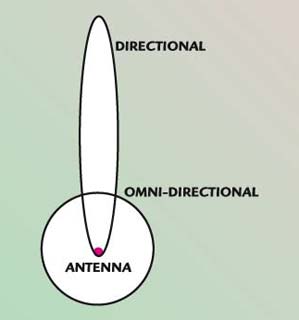
Fig. 1 Antenna radiation patterns.
The antenna gain is actually its directivity at the maximum point, as shown in Figure 1. The radiation pattern is compared to the ideal (isotropic) pattern (there is actually no omni-directional solution to Maxwell equations) and the gain is defined as the extra punch beyond omni, and sometimes measured in dBi (the i for isotropic transmission). The omni-directional antenna is one that transmits all its power equally in all directions. Its power density at range R from the radiator is given by
where
Pt = transmitted power
Note that the total volume in both patterns is similar (???P(R, ?, ?) = total power, is fixed); only one is “bigger” in its radiated direction. This is where the gain (or directivity) is measured.
Now, the antenna cannot deliver all the power, and there is a certain loss associated with this (passive) device. Satcom dishes have efficiencies in the 80 percent range.
In miniature antennas, the efficiency is very small, that is, their radiation pattern can be “omni-directional,” but with significant loss. Losses of 10 to 30 dB are not uncommon, and depend on antenna size relative to wavelength (?) and geometry. In many cases, simple rules determine such critical parameters.
In antenna measurements (once the design is completed, it is taken to a range and measured to show its performance), it is common to measure the field strength. Remember that the conversion from field strength to power is obtained according to
where
E = field strength in V/m
D = distance
P = power
For the popular FCC Part 15 standard, D = 3m, the power as a function of field strength is shown in Figure 2. Note also that the power density is given by E2/(2 • 377).
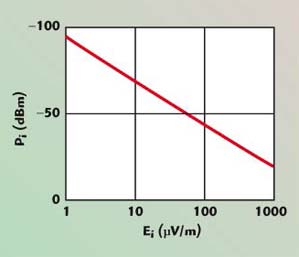
Fig. 2 Power vs. field strength.
Generally speaking, miniature antennas are elements running at or close to resonance. For simplicity, it is assumed that the antenna can be presented as a parallel resonance circuit, with the inductor L, the radiating element (see Figure 3).
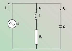
Fig. 3 Miniature antenna model.
The capacitor C resonates the coil, which radiates, and the resistors Rs, shown here in series but which can be represented as a parallel element with the transformation Rp = Rs (1+Q2), determine the resonator (antenna) quality factor Q. If the radio operates at an angular frequency wo, then for a parallel resonance circuit
For example: A 900 MHz antenna, made of a 30 nH coil and 1 pF capacitor, has a Q of 40. Therefore
The impedance of the circuit, resonating at 900 MHz, is shown in Figure 4.
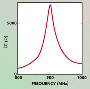
Fig. 4 Antenna circuit impedance resonating at 900 MHz.
The resistor value represents two elements, one dissipating power (mostly heat, due to coil resistance, skin effect and insulator dissipation) and the other part radiating. It is the radiating component that is sought and maximized.
Q is defined as the ratio of the stored-to-dissipated energy. Dissipation occurs for various reasons, including skin effect, dielectric losses, heat dissipation in the coil environment, insulating and shielding. The skin depth in copper is approximately 2.3 mm at 900 MHz and is proportional to 1/?f.
If R = Rd + Rrad (dissipation and radiation resistance), then for a given current Iv through the antenna, the radiated power is given by
![]()
For miniature antennas, Rrad is usually very small compared to Rd. The other interesting point is that in the parallel resonance circuit model, the current through the coil is Q times that of the circuit. Therefore, if the antenna runs at resonance, and if the drive current is Id, then the radiated power is given by
![]()
It becomes immediately obvious that tuning or resonating the antenna is of utmost importance. Certain chips have adaptive mechanisms to perform that function. For printed coils on FR-4, up to 1000 MHz, the Q does not exceed 40 to 50. Air coils can have (unloaded) Qs up to 150. Remember that since the inductance is affected by the self-resonance of the antenna Fc, as in
one should not operate above 40 percent of Fc.
Inductance
For an N turn air loop coil, with a diameter 2r, and a total length l, the inductance is given by

where all dimensions are in mm and the inductance is in nH, as shown in Figure 5 for l = 6 mm and N = 3.
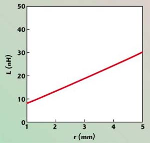
Fig. 5 Air coil inductance vs. coil radius.
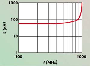
Fig. 6 Effect of the coil self-resonance on the inductance value.
The effect of self resonance on the inductance is shown in Figure 6. In this model, Fc is 1 GHz for a 50 nH inductor. For printed loops with a diameter R, the inductance is given approximately by
![]()
where
r = linear function of the line width
Radiation Resistance
For miniature antennas, Rrad is given approximately by
where
A = area of the coil
N = number of turns
A simulation run is shown in Figure 7, where Rr (Rrad given in dB–?, while the radius of the coil, r, is given in mm), for a 900 MHz design (the wavelength is a foot in free air). For r = 5 mm, the radiation resistance of the coil at 900 MHz is approximately 0.005 ?. The efficiency of such a system can now be calculated.
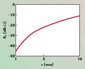
Fig. 7 Radiation resistance of a 900 MHz air coil.
It is assumed that the antenna system has a loaded Q of 30. The coil has a value of ~30 nH, which has an impedance of j130 ?.
Assume that 3V are developed on the antenna. The resistor R has a value of 3900 ?, and the current through the circuit (assuming resonance) is 3/3900 = 0.76 mA. The power dissipated in the resonator is 0.762 × 3900 ~2.25 mW = 3.5 dBm. The current through the coil is Q times higher than in the resistor, ~23 mA, and the radiated power Prad ~0.0232Rrad = –26 dBm. Obviously, the radiation efficiency of this small antenna is very small (~0.1 percent).
Alternatively, the radiation resistance of a printed loop, on a PCB, with a diameter of 30 mm (inductance in the order of 75 nH), with a line thickness of 1 mm, at 900 MHz, is in the order of 0.3 ? and 0.018 ? at 434 MHz. This antenna Q (no ground plane below the antenna printed line) is approximately 40.
Radiation Pattern
These antennas, being much smaller than a wavelength, have no directivity and can provide no protection from multipath by spatial filtering. A typical radiation pattern is shown in Figure 8. It is similar to the radiation pattern of an infinitesimal dipole. The maximum radiation for an air coil is in the coil’s axis plane and the null is perpendicular to that plane.
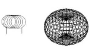
Fig. 8 Radiation pattern of a miniature air coil.
Antenna Diversity and Combining
To mitigate some of the multipath effects, more than a single antenna will be utilized. The basic assumption is that the propagated wave will fade in and out of some of the elements but will be strong enough in others. The combiners then process the array to produce a “good enough” or “optimal” solution.
There are basically three methods for the application of antenna combining for diversity. The principal idea is to use more than one receive antenna, create spatial diversity and somehow combine the RF signals from the various receiving elements such that continuous signal reception shall improve significantly. The three methods are:
- Switch selection — use of a switch to choose an antenna with sufficient power. This is sometimes also referred to as switch diversity, since only one antenna is active in the active received path.
- Regular combining — the signals from various antennas are combined.
- Maximum ratio combining — an optimum, adaptive process is applied, to combine the received signals coherently and optimize the array SNR output.
Of course, there are various combinations of the three, based on requirements, size, power and cost. Many patents and intellectual properties (IP) have been generated in the last few years in this area.
Simple Antenna Combining — Switch Selection
A simple antenna diversity scheme is shown in Figure 9. The system starts with an arbitrary choice, and the switch selects an alternative antenna when the existing power is below a certain level, or, initially, the system can measure the better one and start there. Generally, there is a single receiving path, so the algorithms are rather simple.
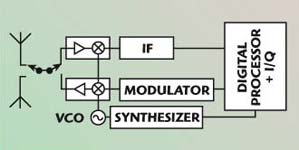
Fig. 9 Simple antenna diversity connected to a transceiver.
The detection algorithm can be based on checking the received signal strength indicator antenna (RSSI) and switching to the alternative antenna when the signal is degrading. The system is simple but effective as an alternative exists when the signal fades out. Note that when switching from antenna to antenna, certain transients and disturbances will occur, especially if it occurs in the middle of a packet or message file.
Adding Combiner
This method employs two (or N, depending on the number of elements) receiving paths that eventually add all signals. As some are fading, others rise, so an improvement is obtained in the overall signal’s availability. There are various nuances to this method, especially with the use of limiters in various areas of the design, as well as enhancement of the stronger signals. However, it will basically provide “strong signal” dominance and is reasonably close to optimum. Certain processing is possible in the individual paths (as has been mentioned already) but, overall, the system will provide dominance to the stronger channels, especially in FM systems, due to capture effect.
Of course, in the case when signals are either in anti-phase and close in amplitude, they can cancel, but statistically and practically, it is almost irrelevant. Figure 10 shows a block diagram of an adding combiner.
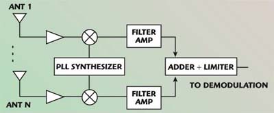
Fig. 10 Adding combiner.
MRC — Optimal Antenna Combining
A more complex operation and an optimum solution can be obtained by processing the array in parallel and combining the result such that better coverage and better SNR are achieved all the time, because the process will enhance the “better” elements dynamically. Such a system shall provide information on relative signal strength and phasing and shall require certain digital signal processing (DSP) in the antenna array processing. An application of such a system is shown in Figure 11 for a personal digital assistant (PDA).
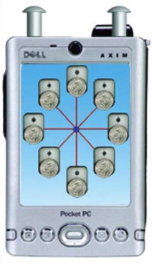
Fig. 11 Antenna combining in a PDA at 2.45 GHz (courtesy of Avaak).
The quarter is there to show size perspective.
As was mentioned already, a certain geometrical separation must be provided, such that a level of “orthogonality” exists between the elements. For example, in the 2.5 GHz ISM band, the separation must be in the order of at least 4" to 5". A certain de-correlation between antennas can be achieved by geometrical alignment, polarization, or slightly changing their field patterns. The array will then be processed as a matrix of signals arriving with various phases and amplitudes according to a certain metric, and required to achieve an optimum (either SNR or interference rejection) performance. For example, in the case of antenna combining, an algorithm should be chosen that collects the signals such that the received SNR be maximized.
Therefore, there is an array of signals, aiej?i, ai and ?i, representing the individual (and dynamic) amplitude and phase of the ith element. Without going through much mathematics, it is intuitive that these signals be added coherently (that is all of them must be rotated to the same phase and then added) and the stronger signal be emphasized while de-emphasizing the weaker one.
One such method optimizes the array performance (assuming that each element has the same noise level) and is called maximum ratio combining (MRC). The technique exercises an optimal (and coherent) solution to antenna combining, which allows more than one antenna to act in concert as an integrated “super antenna,” which adapts its gain (and directivity) to the direction of the “incoming antenna.”
Optimum antenna combining adaptively scales the various antennas such that the overall SNR is maximized. A block diagram of the concept is shown in Figure 12.
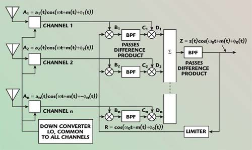
Fig. 12 Closed loop maximum ratio combiner.
A simplified DSP procedure can be applied, either open or closed loop. Today, all processing will be done at baseband, using DSP and therefore improving performance and lowering the specifications of various components (such as bandpass filter group delay and amplitude response).
The beauty of the feedback array lies in the fact that once running, it optimizes the estimate of each element’s amplitude and phase. Similar open loop configurations can be applied too, with similar performance.
If there are N elements and the general output of the array is
(Wi are complex numbers) and the Wi solution that maximizes SNR is sought, using the Schwartz inequality, it is easy to show that the optimum result is achieved for the case
![]()
and
![]()
(where ?o is an arbitrary phase, or it can be the phase of the strongest signal, depending on the processing method).
In most applications, MRC is not used so much for pure antenna gain, but is used to improve coverage as fading effects degrade the reception of some elements but not all. Dynamically, the “center of gravity” will move from element to element.
A transient simulation is shown in Figure 13. Green is the stronger signal, red is the weaker signal and blue is the combined signal. No noise is showing.
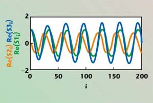
Fig. 13 Simulation of the combining process.
Figure 14 shows a simulation run for the SNRout improvement for antenna 1 with an SNR of 10 dB and antenna 2 with an SNR varying from –10 to 10 dB. For equal signal levels (in this case SNRin is 10 dB), the SNRout will improve by 10 log(N), in this case from 10 to 13 dB. However, as was noticed already, this is not the reason to apply the technique.
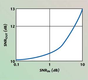
Fig. 14 Two antenna’s SNR.
Needless to say, combinations of the various techniques can be applied to save power. For example, if the signal is strong, connectivity to a single antenna can be maintained, until fading effects are sensed. Then extra antennas and processing can be added. Details of such strategies will not be described here.
Other Options
There are other options for applying antenna diversity, including polarization-sense diversity and element pattern control. Their practicality, however, depends on the size of the antenna (relative to wavelength).
Other Applications
If, for example, two elements are used (for simplicity), and a1,2 and ?1,2 are estimated accurately, then a matrix will be easily built, that will optimally cancel an interfering signal. With N elements, N-1 interferers can be cancelled. The phase of the arriving signals can also be estimated with excellent accuracy, and the direction of the emitter (transmitter) provided for location awareness.
A general processor block diagram for a general adaptive array is shown in Figure 15. The important point here is that a rather small antenna system can achieve what otherwise will require much more space, which is a precious resource in many miniature radio systems emerging now. These systems will then use few radiating elements in combination with DSP, to generate features that can enhance the quality and utility of the overall network of nodes and enable efficiency in communication throughput, interference rejection, directivity, location awareness and overall system performance with low size, low power and reasonable computing power (silicon), hence improved economics and affordability.
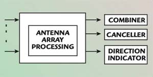
Fig. 15 General adaptive array.
There has been a large volume of work done in the last few years on the networking of large sensor arrays; it is time to also address their electromagnetic aspects. These processing systems, sometimes referred to as MIMO (multiple input, multiple output) arrays, will play a growing role in systems ranging from WiFi to radio sensor networks as density and spectral utility crowds the airwaves and requires extra spatial intelligence and knowledge of location, interference and improved capacity.
Conclusion
Multipath and fading effects are dominating phenomena in wireless communications. Their effect on signal communications quality is of the greatest importance in terrestrial radio communications. Effects of these phenomena can be most effectively mitigated by space diversification and specifically antenna combining.
Few methods, from the simple to the more complex, have been demonstrated for the application of space diversity via antenna combining. The application of the various methods depends on the complexity, power and cost levels available in every system.
The theory of antenna combining is quite well understood, and economical solutions have started to appear in the market, specifically for 802.11 links as well as cell phones. The application of antenna combining in miniature sensor networks and their hubs is also becoming a reality with applications ranging from signal enhancement to localization and spatial filtering. n
References
- Smart Antenna Design, Ansoft Corp.
- “Small Loop Antenna,” Application Note nAN-400-3, Nordic Corp.
- C.A. Balanis, Antenna Theory, Analysis and Design, John Wiley & Sons Inc., 1997.
- L. Besser and R. Gilmore, Practical RF Circuit Design for Modern Wireless Systems, Volume I: Passive Circuits and Systems, Artech House Inc., Norwood, MA, 2003.
- E. Joy, Georgia Tech – CEI, Antenna Seminar Notes, 2003.
- J.D. Kraus, Antennas, McGraw-Hill, New York, NY, 1950.
- Krauss, Bostian and Raab, Solid State Radio Engineering, John Wiley & Sons Inc., 1980.
- “Antenna Selection in Multi-carrier Communications,” Intel Technology Journal, May 2003.
- B.G. Goldberg, “Miniature Radio-sensor Antenna Primer,” Avaak Inc. White Paper.
- C.K Ko and R.D. Murch, “A Diversity Antenna for External Mounting of Wireless Handsets,” IEEE Transactions on Antenna and Propagation, May 2001.