
Enhanced performance is needed from antennas, radomes and other microwave components to support ever-increasing functionality for military communications, electronic warfare (EW), electronic intelligence (ELINT), signal intelligence (SIGINT) and electromagnetic interference (EMI) measurement applications. There is a continuing demand for antennas with broader bandwidth and better controlled radiation patterns while at the same time reducing size and weight. Nurad Technologies is working to satisfy these difficult and sometimes conflicting requirements by developing ultra-broadband spiral antennas and mating radomes that offer high performance over various frequency ranges, sizes and polarizations.
Spiral Antennas
The planar spiral antenna is a member of the class of self-complimentary radiating structures that provide frequency independent performance over wide operational bandwidths. This class includes helix antennas, bowtie dipole antennas and certain log-periodic antennas. The spiral is the most widely used of these antennas because of its compact form factor and generally superior performance characteristics. Spiral antennas have nearly constant input impedance and are capable of VSWR below 2:1 over more than a decade of bandwidth. They can be easily designed for either left-hand or right-hand circular polarization and provide almost perfectly circularly-polarized radiation over their full coverage area, with an axial ratio better than 1 dB on axis. In addition, spiral radiation patterns are nearly constant with frequency. All this can be achieved in a cylindrical volume of approximately 1/3 wavelength diameter by 1/4 wavelength depth.
The most commonly used spiral antenna types are the two-arm equiangular and the two-arm Archimedean planar spirals. The equiangular spiral is a true self-complementary structure where the spiral radius grows logarithmically with rotation angle. The Archimedean spiral has a linear rate of expansion and is not truly frequency independent, but its electrical properties are very similar to those of the equiangular spiral and it is easier to manufacture. Figure 1 shows a family of Archimedean spiral antennas that provide operation over the frequency range of 100 MHz to 40 GHz.

Fig. 1 Cavity-backed spiral antennas for 100 MHz to 40 GHz
These spiral antennas consist of conducting spiral circuits etched on dielectric substrates and fed by internal balun or impedance transformer assemblies. The spirals are mounted atop cylindrical aluminum cavities that are filled with absorbing material, which work together to generate a unidirectional radiation pattern from the otherwise bi-directionally radiating spiral element. They can be used in free space, or installed in conducting ground planes such as the skin of an aircraft or other vehicle, or installed in an absorbing or dielectric structure.
In communication applications spiral antennas are used as single elements, as arrays of elements, or as feeds for reflectors or other high gain apertures. Single elements are ideal for low gain systems where wide angular coverage is needed. Examples include low data rate satellite communications, global positioning system (GPS) and receive-only mobile systems. Spiral arrays and reflector systems are typically used in high gain applications such as high data rate satellite and terrestrial communication networks.
In EW applications spiral antennas are typically used as single elements or in interferometer small arrays. Single elements are used in radar warning systems, SIGINT systems, or low power jamming systems. Interferometer arrays employ a set of a few (typically four) spiral antennas in amplitude or phase-matched sets and are used to determine angle-of-arrival (AOA) of received signals.
Spiral Antenna Size and Gain
Although spiral antennas have nearly constant input impedance over very broad bandwidths, their useful bandwidth is usually limited by radiation efficiency at low frequencies. Most cavity-backed spiral antennas have constant peak gain of approximately 0 to +2 dBiL over a majority of their operational bandwidths. But at frequencies below where the spiral antenna size is less than approximately 1/3 wavelengths in diameter, gain rapidly decreases at a rate of –12 dB/octave. Because of this gain limitation, applications typically use spirals over bandwidths of a decade or less. This is illustrated by the data in Table 1, which lists frequency range, size and nominal gain for a number of different available spiral antennas. The data shows that each antenna has roughly the same gain at its highest frequencies, but that the electrically small spirals have low gain at their lowest frequencies. Note that for narrower bandwidth applications gain can be increased 2 to 3 dB by eliminating absorbing material in the cavity.

Model A4460 Spiral Antenna
The Nurad model A4460 is an example of a spiral antenna that strikes an optimal balance between small size, broad bandwidth and radiation efficiency. As shown in Figure 2, this antenna is a compact cylindrical assembly with an integral balun and a single coaxial connector. This right-hand circularly-polarized antenna is 2 inches in diameter by 1.9 inches deep, operates over the 2 to 40 GHz frequency range with a nominal VSWR of less than 2, and provides high radiation efficiency over the upper end of its 20:1 bandwidth.

Fig. 2 The Nurad A4460 Archimedean spiral antenna.
Radiation Patterns
Typical radiation patterns of the A4460 spiral antenna are shown in Figure 3. These spinning linear polar plots at 2 and 40 GHz exhibit the desired broad beam and symmetric radiation pattern with low axial ratio on axis. The antenna provides coverage over a fairly wide angular region, with 3 dB beamwidths of 102° at 2 GHz and 88° at 40 GHz. Peak gain increases with frequency from –8.0 dBiL at 2 GHz, to 0 dBiL at 40 GHz.
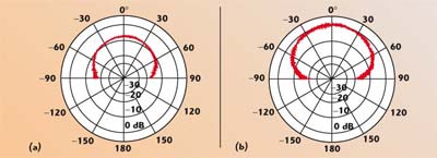
Fig. 3 Radiation patterns of the Nurad A4460 antenna at (a) 2 GHz and (b) 40 GHz.
Conclusion
A series of high performance spiral antennas has been developed for EW and communication applications. The new model A4460 cavity-backed spiral antenna operates over the 2 to 40 GHz frequency range, providing excellent radiation performance over the entire 20:1 bandwidth. It is suitable for use in the extreme environment of high dynamic airborne flight, for which a protective radome can be included for a complete airborne antenna system. In addition, it can be used in matched sets of phase or amplitude tracking units for angle-of-arrival detection systems.
Nurad Technologies Inc.,
a division of Chelton Microwave Corp.,
Baltimore, MD
(410) 542-1700,
www.cheltonmicrowave.com.