Size, cost and performance pressures have driven the industry to ever higher levels of RF integration. Dramatic progress has been made in the integration of the active functions but general adoption of passive integration (integrating functions such as RF filters, diplexers and baluns) has lagged behind. The industry has long sought an organic laminate-based alternative to the LTCC (low temperature co-fired ceramic) solutions that dominate the market. Laminates are a proven, reliable technology, but FR4-based solutions have historically exhibited inferior RF performance and high performance laminates have been too expensive.

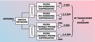
Fig. 1 A dual-band wireless LAN RF front end.
JMD has released a new non-ceramic, laminate-based RF integrated passive device, the I3002. The device integrates two diplexers, two transmit filters and two receive filters in a 3.3 × 7 × 0.65 mm package. The product is targeted at IEEE 802.11 b/g/a wireless LAN applications that operate in the 2.4 to 2.5 GHz and 4.9 to 5.9 GHz bands. The technology exhibits higher Qs and lower insertion losses than has been previously achievable in competitively priced laminates.
The Problem
Figure 1 shows the block diagram for a typical dual-band wireless LAN application. In addition to the power amplifiers (PA), low noise amplifiers (LNA) and switches, there are six key passive components, two diplexers and four RF filters. On the transmit side the output of the 2.4 GHz PA and 5 GHz PA must be filtered to eliminate images of the desired signal that appear at the second and third harmonic. These images must be attenuated sufficiently to meet the FCC transmit spectrum masks. The exact attenuation requirements are dependent on the PA linearity and to a lesser degree the RF transceiver and other circuits. Typical applications require attenuation of 35 dB at the second harmonic and 20 dB attenuation at the third harmonic.

Fig. 2 A WLAN RF front end with the I3002 integrated passive device.
The transmit diplexer allows the two frequency bands to share the same antenna. The receive diplexer performs the same function for the receive path. Each receive path has a filter whose principal function is to block interference from the mobile phone bands.

Fig. 3 The I3002 IPD’s transmit path.

Fig. 4 The I3002 IPD’s receive path.
A New Solution
The I3002 device integrates both diplexers and all four filters into a single 3.3 × 7 × 0.65 mm component, as shown in Figure 2. A typical design with individual filter and diplexer componets would require 10 × 20 mm of board space. The I3002 is fully shielded, which enables further space savings by allowing the device to be mounted in close proximity to other components. The component has LGA (land grid array) I/O pads on the bottom for mounting to the user’s circuit board.
The performance parameters for the full transmit and receive paths are shown in Table 1. The data shows the combined effect of the filters and the diplexer for each path. This performance meets the attenuation requirements for WLAN applications with low insertion loss. Typical passband characteristics for the transmit and receive paths are shown graphically in Figures 3 and 4, respectively. This technology is also used for RF modules. In this case the PA, switch and other RF die are mounted on the top of the component and the RF passive functions are embedded in the substrate.

Conclusion
JMD’s new patent pending technology provides the RF industry with a platform for embedding RF passives (RF filters, diplexer, baluns, etc.) to create integrated passive devices (IPD) and RF module substrates. The technology combines the proven reliability of laminates with size and price that are competitive in the mobile handset and wireless LAN markets.
Jacket Micro Devices Inc. (JMD),
Atlanta, GA
(404) 526-6043,
www.jacketmicro.com
