
The United States Federal Communications Commission (FCC) has opened the radio spectrum from 3.1 to 10.6 GHz, permitting the use of a new unlicensed radio transmission technology, the UWB system. UWB systems entail sharp sub-nanosecond pulses, and occupy a wide band with the only restriction being a limit on the radiated emissions levels. The European Commission is following the same road and has been allocating the bands from 3.4 to 9 GHz for UWB systems.1 Several compact UWB antennas have been reported.2-5,7
In this article, a compact planar monopole antenna is proposed for UWB operation. The proposed antenna uses an SMA connector in place of a ground plane. Details of the antenna design and experimental results are presented and discussed.
Antenna Design
Figure 1 shows the geometry of the proposed antenna. The antenna is printed on a FR4 substrate, with a relative permittivity of 4.4 and a thickness of 1.6 mm, and mounted on the square flange of an SMA connector, with a width of 12.7 mm. The antenna consists of three sections: a planar monopole, a microstrip line and an SMA connector.
Figure 1 Geometry of the proposed antenna: (a) top view, (b) SMA connector and (c) sectional view.
Planar monopole antennas, featuring broad bandwidth, small size, omni-directional radiation pattern and low cost, have been proposed and investigated for UWB applications.2,3 Therefore, a rectangular planar monopole (12.8 mm × PW) is used. In addition, a line (IL × IW) is situated between the planar monopole and the microstrip line to achieve good impedance matching.
The antenna is fed by a microstrip line 3.19 mm wide. The microstrip line is connected to the 1.3 mm diameter inner conductor of an SMA connector and a 1.7 mm diameter circular patch is printed around the via-hole for a smooth connection. The ground plane of the antenna is the ground flange of the SMA connector that has the dimensions of 12.7 × 12.7 mm. Therefore, the proposed antenna is designed to connect the main radiator directly to the SMA connector without a special ground plane.
Planar antennas with a modified ground plane (beveling and notch) have been proposed and investigated for UWB operation.4,5,7 In the case of the proposed antenna, the SMA connector has bevels (with a width of 1.35 mm and a 45-degree angle) at each corner for broadband operation. Incorporation of the four circular holes of the SMA connector does not have a significant influence on the operating performance of the antenna.
Discussion and Experimental Results
For a printed rectangular planar monopole antenna, the impedance bandwidth is heavily dependent on the width of the monopole.6 Figure 2 shows the simulated voltage standing wave ratio (VSWR) of the antennas for various widths PW, keeping IW = 0.35 mm and IL = 1.3 mm constant. Varying PW from 1.5 to 9.5 mm yields results similar to those of Jhon and Amman.6 Good impedance matching can generally be implemented only when PW is equal to 5.5 mm, at which value the impedance bandwidth covers the UWB band (3.1 to 10.6 GHz).
Figure 2 Simulated VSWR for various widths PW.
A small transmission line is located between the planar monopole and the microstrip line to achieve good impedance matching. Figure 3 shows the VSWR of the antennas with various widths IW, keeping PW = 5.5 mm and IL = 1.3 mm constant. Figure 4 shows the VSWR of the antennas with various lengths IL, keeping PW = 5.5 mm and IW = 0.35 mm constant. The final dimensions IW and IL are set at 0.35 and 1.3 mm, respectively, in order to cover the UWB band.
Figure 3 Simulated VSWR for various widths IW.
Figure 4 Simulated VSWR for various lengths IL.
The antenna was fabricated and measured. Figure 5 shows a photograph of the fabricated antenna. Figure 6, which shows the simulated and measured VSWR for the given dimensions, confirms the good agreement between the measured and simulated results. The simulated and the measured bandwidth, defined by VSWR less than 2:1, were 7.63 GHz (3.09 to 10.72 GHz) and 7.74 GHz (3.06 to 10.80 GHz), respectively.
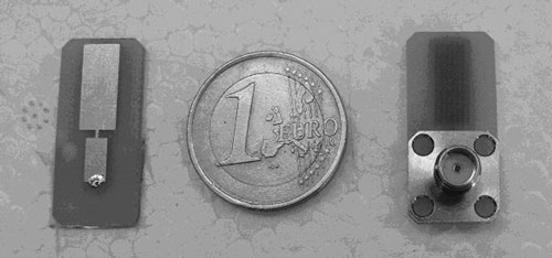
Figure 5 Photograph of the fabricated antenna.
Figure 6 Simulated and measured VSWR of the fabricated antenna.
Figure 7 shows the measured group delay in the time domain. The antennas were separated by a distance of 50 mm due to the low output power of the network analyzer. The group delay is not well detected by the network analyzer at a significant distance, without a low noise amplifier (LNA).7 Considering the measured values in an available range of UWB communication, from 3.1 to 10.6 GHz, the group delay variation was less than approximately 1 ns. This performance should allow for communication through enhanced phase linearity, and a pulse template transmitted or received by the antenna will retain its shape without serious distortion. The magnitude of transmission loss (S21) between two identical antennas separated by 100 mm was also measured and is plotted in Figure 8. For measurement of group delay and S21, an antenna was connected to each port of the network analyzer, and both identical antenna pairs were placed front to front, front to side, and side to side. In the figures, the markers indicate the frequency points at 3.1 and 10.6 GHz, respectively.
Figure 7 Group delay measured in the time domain.
Figure 8 Measured transmission loss.
Conclusion
A compact planar monopole antenna with an SMA connector has been proposed for UWB operation. The proposed antenna uses an SMA connector in place of a ground plane. As a result, broad impedance bandwidth and compact antenna dimensions are achieved. The measured VSWR, transmission loss and group delay demonstrate that the antenna can serve for UWB operations. The proposed antenna has small dimensions, broad impedance bandwidth, small group delay, and is suitable for UWB antenna applications.
References
1. S. Bruni, A. Neto and F. Marliani, “The Ultra-wideband Leaky Lens Antenna,” IEEE Transactions on Antennas and Propagation, Vol. 55, No. 10, October 2007, pp. 2642-2653.
2. Z.N. Chen, “Novel Bi-arm Rolled Monopole for UWB Applications,” IEEE Transactions on Antennas and Propagation, Vol. 53, No. 2, February 2005, pp. 672-677.
3. X.H. Wu and Z.N. Chen, “Comparison of Planar Dipoles in UWB Applications,” IEEE Transactions on Antennas and Propagation, Vol. 53, No. 6, June 2005, pp. 1973-1983.
4. J. Jung, H. Lee and Y. Lim, “Compact Band-notched Ultra-wideband Antenna,” Electronics Letters, Vol. 44, No. 6, March 13, 2008, pp. 391-392.
5. C.Y. Hong, C.W. Ling, I.Y. Tarn and S.J. Chung, “Design of a Planar Ultra-wideband Antenna with a New Band-notch Structure,” IEEE Transactions on Antennas and Propagation, Vol. 55, No. 12, December 2007, pp. 3391-3397.
6. M. Jhon and M.J. Ammann, “Optimization of Impedance Bandwidth for the Printed Rectangular Monopole Antenna,” Microwave and Optical Technology Letters, Vol. 47, No. 2, 20 October 2005, pp. 153-154.
7. Y.J. Cho, K.H. Kim, D.H. Choi, S.S. Lee and S.O. Park, “A Miniature UWB Planar Monopole Antenna with 5 GHz Band-rejection Filter and the Time-domain Characteristics,” IEEE Transactions on Antennas and Propagation, Vol. 54, No. 5, May 2006, pp. 1453-1460.