
Several years ago, a new antenna was developed to address the increasing need for compact wideband antennas.1,2 The new antenna was presented as a novel spiral configuration best described as a Tapered Area Small Helix (TASH). The original work drew the interest of the US Army Communications — Electronics Research Development and Engineering Center (CERDEC), Ft. Monmouth, NJ, an Army agency requiring wideband low profile antennas. At CERDEC’s request, one of the original TASH monopoles was provided for field evaluation. The results were encouraging enough that a proposal was requested for frequency extension of the basic TASH monopole structure. A proposal to optimize the VSWR bandwidth of the TASH antenna was accepted. The accepted proposal had several interrelated objectives. The first objective was to determine if a TASH monopole antenna could provide a low VSWR over much more than an octave band, and if so, what limitations exist. Once the antenna limitations were understood, a set of design guidelines was developed to produce a TASH monopole for any desired frequency range. The final objective was to use the design guidelines to design, assemble and test one or more prototype antennas suitable for field demonstration of wideband performance over the 225 to 2000 MHz range. Comparison tests were to be performed by a government agency after delivery of the prototype antennas.
Technical Approach
The initial task was to define the technical requirements for the desired TASH antenna covering the 225 to 2000 MHz range. The technical approach to meet those requirements was to perform both computer simulation and hardware verification of potential TASH configurations. The prior 225 to 450 MHz TASH antenna work1 was used as a starting point. Prior work showed that a TASH monopole of 1.5 to 2.0 turns would give a higher VSWR than a 2- to 3-turn TASH monopole, but with much wider bandwidth. It was also noticed that many versions of 10:1 height to diameter ratio TASH monopoles (225 to 450 MHz designs) had low VSWR except for a single region one to two octaves above the lowest useful frequency. These observations and a comparison antenna were used as a baseline for a series of simulations.
The comparison antenna for the TASH frequency extension effort was the discone. The discone is an unbalanced, single polarization radiator capable of VSWR less than 3:1 over more than four octaves. Other antennas in the discone family include the bicone and single cone above a ground plane. All these antennas are capable of low VSWR over wide bandwidths, although the discone is probably more popular because it can be used with or without a ground plane. Discone VSWR and radiation characteristics represented the wideband performance goals for the wideband TASH monopole.
Simulation
Eventually, hundreds of GNEC-4 and WIPL-D (another MoM software application) simulations were run to evaluate the VSWR bandwidth of various TASH antenna configurations. In early simulations, it was found that the base length-to-height ratio of the triangular TASH element could be varied to produce many simulations with low VSWR. The ratio was consequently reduced to produce the minimum element area still capable of low VSWR over the 225 to 2000 MHz range. The thinking was that it would be more difficult to reproduce a large area element than a smaller one, even though the rolled diameter might be the same. Using this approach, several simulations were produced that gave acceptable results (nominal 3:1 VSWR or less from 225 to 2000 MHz).
One of the early configurations representative of these simulations is shown in Figure 1. The simulated element height is 0.295 m and the diameter 0.165 m. The simulated VSWR for that configuration is shown in Figure 2. Further simulations were performed in conjunction with brass board measurements resulting in further antenna size reduction and improved VSWR.
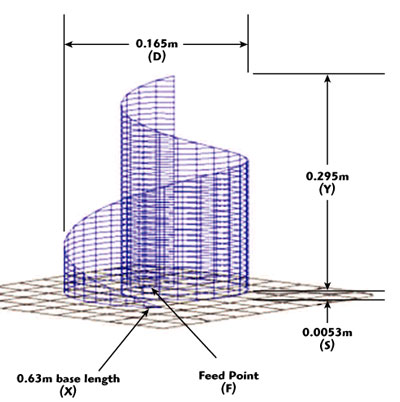
Fig. 1 Early configuration of a 225 to 2000 MHz TASH monopole.
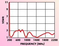
Fig. 2 Simulated VSWR versus frequency for the early TASH monopole.
Simulation results showed that a low VSWR (< 3) was possible only when the diameter of the TASH element was large (0.5 to 1.0 times the TASH element height). The spiral spacing did not affect the VSWR significantly (increase more than 3) if the diameter was within 50 ±10 percent of the element height. It was found that the spacing from the ground plane was more important. A spacing of the order of two percent of the TASH element height produced the lowest wideband VSWR. Lower or higher percentage spacings degraded the VSWR at some frequencies over a 10 to 1 range. The feed point location on the TASH element base is the most critical parameter of a TASH monopole simulation. Varying the feed point location essentially varies the current distribution on the TASH element. Moving the feed point toward the center of the base (x-y intersection) results in high VSWR over a narrow frequency range near the lower end of the band of interest. The VSWR becomes better and the poor VSWR frequency range narrower as the feed point is moved away from the center. A feed point can usually be found where the VSWR is acceptable (< 3) at most frequencies over at least a 10 to 1 range.
Design Optimization
The measurements made during the project were primarily input VSWR and radiation antenna patterns over the frequency range of interest. A number of tests were performed on TASH antennas mounted on a small laboratory (indoor) ground plane and a large outdoor ground plane. VSWR measurement of various TASH configurations and brass boards were initially performed in the laboratory on a small ground plane. If the configuration showed promise, then additional tests were performed on a large outdoor ground plane to validate the simulation results. Good VSWR correlation was found between simulation and measurements on a small ground plane (0.47 × 0.56 m) and an outdoor ground plane VSWR over the full 225 to 2000 MHz range.
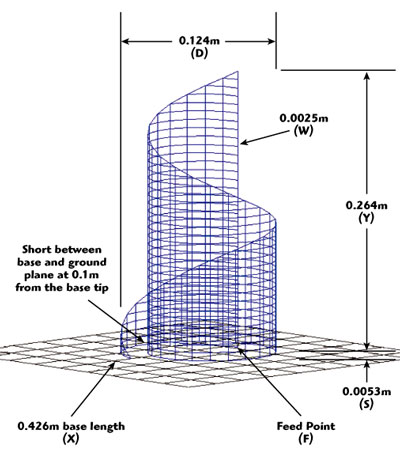
Fig. 3 Reduced size 225 to 2000 MHz TASH monopole.
Initial simulations concentrated on TASH monopoles with height-to-diameter ratios of 5 to 10. It was later discovered that the ratio should be on the order of 2 to remove the high VSWR condition above the first octave. After many simulations and brass board measurements, the focus was on VSWR optimization of two TASH monopole configurations. The first configuration was a 1.8 height-to-diameter TASH monopole fed at a point approximately 10 to 20 percent in from the vertical edge on the base spiral. The second configuration was also approximately 2 in height-to-diameter, but of smaller volume. The second configuration, as shown in Figure 3, differed from the first in that it was fed at the base of the vertical edge, although the base was also shorted to the ground plane approximately 25 percent in from the base tip. This second configuration was selected as the final prototype configuration primarily because of its smaller volume. Figure 4 is a simulated VSWR versus frequency plot for this second configuration; Figure 5 is a measurement of the prototype configured as in the simulation.
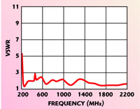
Fig. 4 Simulated VSWR versus frequency for the reduced size TASH monopole.
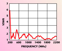
Fig. 5 Measured VSWR versus frequency for the reduced size TASH monopole.
Radiation
The radiation from a TASH antenna is complex. In addition to linear monopole mode and helical modes of radiation, the TASH structure supports a third radiation mode, exemplified by a class of antennas known as transmission line antennas. Examples of transmission line antennas include the well known “towel bar” antenna and the directly driven resonant radiator (DDRR) antenna.3–5 The directly driven resonant radiator antenna is a type of transmission line antenna characterized by its compact size compared to its radiation wavelength. DDRR antennas are often produced in a spiral pattern, since the interaction between the conductors is minimal if the spacing is less than 2.5 times the spacing of the transmission line (element base) to the ground plane. Ground plane-to-element spacing of the TASH monopole is generally similar to the spacing found in spiral transmission line antennas (0.002 to 0.01 wavelengths). The transmission line mode of the TASH monopole antenna produces vertically polarized radiation at frequencies above the first resonance of the TASH base spiral. This is illustrated by the diagram in Figure 6, which shows the relative radiation contribution of each mode.
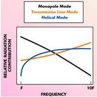
Fig. 6 Relative radiated power contribution for each TASH mode versus frequency.
Another way to analyze the TASH antenna is to consider the base spiral as a continuously tapped transmission line feeding contiguous vertical elements of varying length. The transmission line is optimized to feed each element at the proper phase for minimum VSWR over the bandwidth of interest.
The radiation patterns of 225 to 2000 MHz TASH monopoles were investigated by both simulation and measurement. Figures 7 and 8 show three-dimensional radiation patterns for a TASH monopole from GNEC-4 and WIPL-D simulation software, respectively. Inspection of a series of radiation patterns from WIPL-D and GNEC-4 in addition to the measured patterns indicates that the TASH antenna radiation is similar to a linear wideband antenna, such as the discone, at frequencies within the lowest frequency octave. At higher frequencies it was verified that the TASH monopole produces both axial and linear radiation with pattern irregularities at the highest frequencies (1000 to 2000 MHz). At the higher frequencies, the pattern irregularities are significant (> 3 dB), but not as great as the elevation nulls observed in conventional monopole and discone radiation patterns. Figure 9 shows WIPL-D TASH three-dimensional radiation patterns at frequencies between 200 and 1800 MHz.
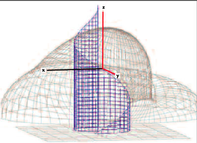
Fig. 7 TASH monopole three-dimensional radiation pattern at 850 MHz (GNEC-4).
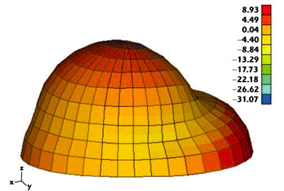
Fig. 8 TASH monopole three-dimensional radiation pattern at 850 MHz (WIPL-D)
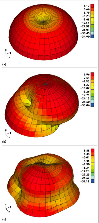
Fig. 9 Simulated (WIPL-D) TASH monopole radiation patterns at (a) 200, (b) 1000 and (c) 1800 MHz.
The radiation pattern of the completed 225 to 2000 MHz prototype TASH monopole was measured in an anechoic chamber over the full frequency range. A calibrated turntable (0.33 × 0.36 m ground plane) rotated the antenna at a point 4.9 meters from a receiving antenna. The receiving antenna was a wideband discone covering the same frequency range as the TASH antenna under test. The discone is only sensitive to linear polarization. Therefore, the patterns measured at frequencies more than an octave above 225 MHz did not include contributions from other than linear radiation. Figure 10 shows the 225 to 2000 MHz prototype TASH antenna on the turntable. Figure 11 is a measured example of the azimuth pattern referenced to a discone.
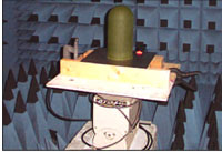
Fig. 10 TASH monopole mounted in the anechoic chamber for azimuth pattern measurements.
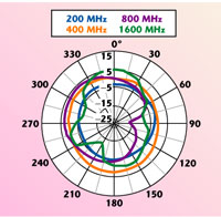
Fig. 11 TASH monopole azimuth pattern measured at 0 elevation at various frequencies.
Even though measurements were made in the near field at low frequencies (200 to 400 MHz), the pattern was essentially omni-directional where the anechoic chamber performance was poor. The pattern developed irregularities as the frequency increased, which was in good agreement with simulated pattern data.
Prototype Design
A TASH prototype antenna evolved as simulation analysis and brass board measurements converged on a design capable of low VSWR over the 225 to 2000 MHz range. The final TASH 225 to 2000 MHz monopole antenna, resulting from the design effort, was built with a height-to-diameter ratio of approximately 2. The element consisted of a triangular sheet of copper mesh 0.259 m (0.2 l) high and a base of 0.42 m (0.32 l) rolled, as shown in Figure 12. The element was mounted on a base plate with the feed point at the inner most edge of the base spiral and shorted to the ground plane (base plate) approximately 0.1 m (0.08 l) in from the base tip. The spacing to the ground plane was 0.005 m (0.004 l). Figure 13 shows the finished prototype antenna element with its radome removed.
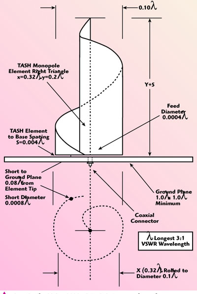
Fig. 12 The 225 to 2000 MHz TASH monopole configuration.
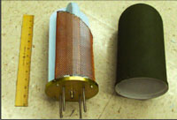
Fig. 13 Prototype TASH monopole element with radome removed.
Figure 14 shows the complete 225 to 2000 MHz prototype antenna installed on a large outdoor ground plane. After installation no adjustments were made to the antenna prior to measurement. The measured VSWR and impedance results are shown in Figures 15 and 16, respectively.
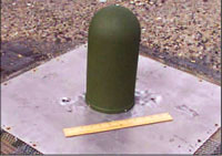
Fig. 14 Complete TASH 225 to 2000 MHz prototype on an outdoor ground plane.
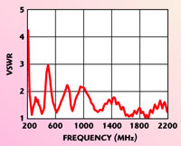
Fig. 15 Measured VSWR of the TASH 225 to 2000 MHz prototype on an outdoor ground plane.
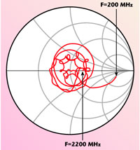
Fig. 16 Measured impedance of the TASH 225 to 2000 MHz prototype on an outdoor ground plane.
Design Issues
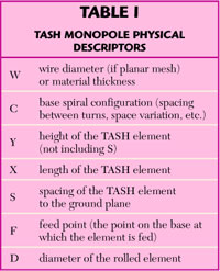
Although the TASH antenna is inherently simple, the asymmetry of the TASH element makes construction slightly more complicated than would be the case for symmetrical antennas such as discones. However, once the mechanical design has been established, it is no more difficult to fabricate TASH monopoles than other antenna types. The electrical design of a conventional TASH monopole generally follows the method shown in this article and as described in Table 1.
The primary TASH antenna variables are element height, base length, outside diameter, base-to-ground spacing, base pattern and feed point. Through simulation and measurement it was determined that the overall length of the TASH element establishes the lowest 50 W VSWR in a 10:1 bandwidth. Typically, the lowest frequency with a VSWR of 3 will be set by the overall height of the TASH element Y plus the element-to-ground spacing S. The total of Y+S will equal approximately 0.2 l. To some extent the lowest frequency is also a function of the diameter D of the TASH element. For height-to-diameter ratios ranging from 2:1 to 1:2, the lowest frequency will decrease as the height-to-diameter ratio decreases.
A TASH element base length of almost any value X produces multiple transmission line resonances as the frequency increases. For longer base lengths, more resonances will be produced for a given bandwidth. Although a large number of resonances improves cancellation of the reactance, the extra complexity of the additional length can be challenging to control and reproduce. The best element base length for reproducibility is the minimum length that produces acceptable VSWR over the design bandwidth. Lengths of 1.5 to 2.5 times the element height are typical. For the shorted base final prototype the base length X was 0.32 l. For TASH monopoles in general, the outside diameter is limited by the length of the element base X as rolled to form the minimum diameter possible for the desired bandwidth.
The base-to-ground spacing S affects the characteristic impedance of the transmission line mode. The nominal spacing should be 0.4 ±0.2 percent of the longest wavelength l of interest. Although VSWR is a function of the spacing between the TASH element turns, the effect on VSWR is minimal over that range. Less spacing reduces the high frequency VSWR while increasing the low frequency VSWR and vice versa.
The primary feed point can be at any point on the base of the element. The bottom of the innermost edge generally provides a good feed point for TASH element heights that are nominally a quarter wavelength at the lowest frequency of interest. For shorter height TASH elements a feed point approximately 10 percent of the base length for each 10 percent reduction in element height will give the best match to 50 W. However, the overall VSWR becomes worse as the element height is reduced further.
Mechanically, the TASH element can be either a solid planar surface or a grid structure. A grid surface should have grids with dimension less than 0.1 wavelengths at the highest frequency of interest. Grid surfaces offer several other advantages. They are generally lighter and easier to shape than solid planar surfaces. When encapsulated the mesh allows the encapsulating material to flow freely within and around the element. They also correlate well with grid simulation models.
The TASH element has a significant mechanical advantage over most linear wideband antennas (cone, discone and capped cone). The majority of the TASH element mass is located at the base. This makes it easy to fabricate a ridged antenna by attaching the TASH element to the base using dielectric spacers. The spiral structure is much more stable than that for comparable wideband omni-directional antennas.
The feed point diameter is normally not critical unless a short is placed between the TASH element and the ground plane, in which case the feed point diameter to short diameter ratio becomes a factor in establishing the characteristic impedance within the first octave.
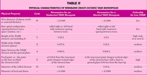
A short to ground along the base offers some advantages. The short allows direct mechanical connection to the base ground plane, which provided another rigid support for the TASH spiral element. It also reduces the potential for damage to equipment connected to the TASH element should high voltage be inadvertently applied or induced into the TASH element. Table 2 summarizes the physical characteristics of the wideband TASH monopoles as currently optimized.
Although the optimization effort concentrated on the 225 to 2000 MHz range, it was determined that the TASH structure has the potential for much wider bandwidth. Figure 17, for example, shows the simulated VSWR of a TASH monopole configuration over the 100 to 8100 MHz range.
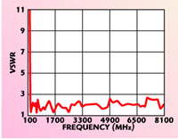
Fig. 17 GNEC-4 simulated wideband VSWR of a TASH antenna.
Conclusion
The TASH monopole represents a new class of composite antennas combining the radiation modes of several basic antenna elements in one structure. Through measurement and simulation it was concluded that the radiation pattern of a TASH monopole is predominately linear at frequencies within the first octave above c/l with some circular polarization even at frequencies above c/l. However, a large percentage of the radiation remains linear and omni-directional at frequencies well above c/l. The radiation pattern is less affected by ground plane size and irregularities than comparable wideband antennas such as the discone.
Acknowledgments
The author wishes to thank the US Army CERDEC for supporting this work. Particular thanks go to both Steve Goodall and Yoram Levy of CERDEC for their technical support and continuing interest in this antenna development.
References
1. T.J. Warnagiris, “A Monopole with a Twist,” Microwave Journal, Vol. 44, No. 9, September 2001, pp. 120–137.
2. T.J. Warnagiris, “Wide Bandwidth Multi-mode Antenna,” Patent No. 6,339,409, January 15,2002.
3. R.W. Burton and R.W. King, “Theoretical Considerations and Experimental Results for the Hula-hoop Antenna,” Microwave Journal, Vol. 6, No. 11, November 1963, pp. 89–90.
4. R.D. Wanselow and D.W. Milligan, “A Compact, Low Profile, Transmission Line Antenna-tunable Over Greater than Octave Bandwidth,” IEEE Transactions on Antennas and Propagation, Vol. 14, No. 6, November 1966, pp. 701–707.
5. R.C. Fenwick, “A New Class of Electrically Small Antennas,” IEEE Transactions on Antennas and Propagation, Vol. 13, No. 3, May 1965, pp. 379–383.
Tom Warnagiris received his BSEE degree from Pennsylvania State University and has performed graduate work at the University of South Florida. He is currently a staff engineer in the Signal Exploitation and Geolocation Division of the Southwest Research Institute. He previously worked as an engineer at ARINC Research, the ECI Division of NCR, C-COR Electronics and HRB Singer. He holds several communications related patents and is a registered engineer in both Pennsylvania and Florida.