
The demand for smaller communication devices for personal communication systems has led to a constant search for methods to reduce the cellular phone dimensions. However, the wavelength does not decrease with the same speed as the size of the mobile phones due to the higher frequency bands used. Even a quarter wavelength antenna, such as the planar inverted-F antenna (PIFA) tends to become too large, thus creating a demand to decrease the volume of the antenna. Size reduction can be accomplished simply by shortening the antenna. However, at lengths shorter than the resonant length, the radiation resistance changes, and the impedance at the terminals of the antenna become reactive. The latter can be compensated for by the use of one or more inductors connected in series with the antenna for cancellation of the capacitance, thus improving the impedance match1 and ultimately the efficiency.2 The idea of using a lumped inductor in conjunction with an antenna has often been used in connection with low frequency antennas where the physical size might be several hundred meters.3 To date, however, it has found very little use in mobile telephony.4
It has been demonstrated3,4 that the highest advantage is gained by placing the inductor at the center of each antenna arm, instead of at the input. In this article, the results of investigations regarding both the location of the inductor as well as the inductance value are presented. For many practical applications, it is more suitable to place the inductor almost at the input. In this way, no inductor is located on the antenna element itself, but rather on the supporting structure or on the ground plane. In fact, the main objective of this article is to present the results of numerical and experimental investigations of the size reduction of a PIFA by the use of a lumped inductor. As an intermediate target, the aim is to reduce the center frequency by 33 percent for a fixed physical size of the antenna. The antenna performance, in terms of the radiation properties, scattering parameters, electrical near-field distribution and current distribution, is simulated and verified by measurements.5-8 The evaluation of the antennas in terms of the electrical field distribution and current distribution on the antenna element as well as on the ground plane has been accomplished using planar near-field measurements.9–12 The near-field is usually transformed to far-field data. Nevertheless, it is the raw unprocessed near-field data that is presented and used in this article.
Materials and Methods
The antenna configuration considered consists of a 40 mm long, 1.5 mm wide and 5 mm high PIFA located on a 40 mm × 100 mm ground plane. In all the prototypes, Rohacell material (?r = 1.06) is used as the supporting structure of the antenna. The antenna is located at the edge and parallel to the 100 mm edge, as illustrated in Figure 1. The feed point is located 5 mm from the edge where a 90° bend forms the short to the ground plane. In the cases where the inductor is incorporated on the antenna element, a 0.5 mm wide gap is cut in the antenna arm. In order to determine the optimal set-up with respect to the antenna performance, the location of the inductor is varied. Hence, the cut is moved from almost at the feed point, the 0.5 mm case, towards the open end, the 33 mm case.
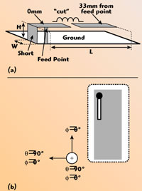
Fig. 1 Schematic of the PIFA located above a ground plane (a), and antenna orientation in spherical coordinates (b).
A planar scanner is used to perform the measurements.7 The step size is 4 mm leading to a total of 496 measurement points for a 60 mm × 120 mm area. This area covers the ground plane plus an additional 10 mm on each side of the ground plane.9 A three-dimensional E-field probe is used for these measurements. The probe is designed for electrical near-field component measurements up to 3 GHz.8 The measurements are carried out at 1.06 GHz, that is, the measured centre frequency (|S11|min) of both the 40 mm loaded as well as the 60 mm unloaded antenna. The measurement facility gives the total amplitude of the electrical fields. These measurements are compared to results obtained from the IE3D computer program used.6
In the planar scanning technique the probe is moved in a plane situated in front of the antenna and the received signal (amplitude) is recorded. The position of the probe is characterised by the coordinates (x, y, z0) in the xyz coordinate system of the antenna. During the scanning, z0 is kept constant, while x and y is varied. The field is measured at a distance z0 = 3.2 mm, which corresponds to a free space distance of ?o/90, equivalent to an electrical length of 4°. It should be noted that the distance between the ground plane and the measurement plane is 8.2 mm (?o/35), since the antenna height is 5 mm.
The Unloaded PIFA
In order to validate the performance of the loaded antennas, an unloaded prototype having the same dimension has been fabricated (L × W × H) = (40 mm × 1.5 mm × 5 mm). This antenna has a somewhat higher centre frequency compared to the loaded antennas. Therefore, a larger unloaded antenna that has the same centre frequency (|S11|min) as the loaded antenna is also presented (60 mm × 1.5 mm × 5 mm). In this way, a more realistic comparison can be made.
The simulated and measured reflection coefficient and radiation efficiency for two unloaded antennas, 40 mm and 60 mm, are shown in Figure 2. For the 60 mm PIFA the simulated centre frequency (|S11|min) is 1.2 GHz, 33 percent lower than the centre frequency (|S11|min) for the 40 mm long PIFA, which is 1.8 GHz.

Fig. 2 Simulated and measured reflection coefficient and radiation efficiency for the unloaded 40 mm (a) and unloaded 60 mm (b) long PIFAs.
For both antennas, the measured frequencies with the lowest reflection coefficient are approximately 10 percent lower than the simulated results. This difference could be caused by a slight difference in the simulated model and the prototype. The resolution used in the simulation can also cause some discrepancy. Here, converged results are obtained using 20 cells per wavelength and edge cells.6
The measured total electrical field components of the radiation patterns for the 60 mm unloaded PIFA, shown in Figure 3, indicate good agreement between the simulated and the measured results. Note that the radiation patterns are obtained at the centre frequency (|S11|min); therefore, the simulated patterns are at 1.23 GHz and the measured ones at 1.06 GHz. The measured maximum gain is 3.9 dBi, slightly higher than the simulated gain.

Fig. 3 Total electrical field components of the radiation patterns for the 60 mm unloaded PIFA; (a) ? cuts for ?=0°, (b) for ?=90° and (c) ? cut for ? =90°
The total electrical near-field distribution at a distance of z0 = 3.2 mm above the antenna element is shown in Figure 4. Good agreement in terms of peak amplitude and shape of the electrical near-field distribution between the simulated and the measured results are obtained; however, more details could be observed from the simulated result. For instance, when observing just above the radiating element, especially at (x, y) = (0, 40–70), a local minimum is found and the edge peak radiation is higher above the ground when compared to that obtained at the side of the ground plane. This is also in accordance with the measured radiation pattern shown previously. In both cases, the peak values are associated with the open end of the antenna, that is at (x, y) = (0, 40). Also, in both cases a minimum is observed at (x, y) = (40, 40), that is at the opposite edge of the PIFA.
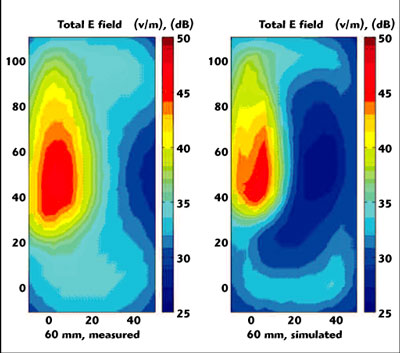
Fig. 4 Measured and dimulated total electrical near-field distribution for the 60 mm long inloaded PIFA at 1.06 GHz.
Either an inductor or a capacitor can be used to reduce the centre frequency (|S11|min) from 1.8 GHz as for the 40 mm long PIFA to 1.2 GHz. This frequency reduction corresponds to a size reduction of 33 percent, that is from 60 mm to 40 mm.
Inductor-loaded PIFA
Two different tests are made. First, for a fixed location of the inductor, the inductance is varied between 5 and 100 nH. Hereafter, the optimal location is found for a fixed inductance value.
Numerical Results
Locating an inductor 10 mm from the feed point forms the inductor loading. For this fixed location, the simulation results for varying the inductor value between 5 and 100 nH are shown in Figure 5. Here, the centre frequency (|S11|min) and the bandwidth are plotted with respect to the 40 mm unloaded case. The centre frequency (|S11|min) drops from 1.8 GHz towards 0.87 GHz for inductor values above 70 nH. For values above 35 nH, however, the bandwidth is lower than for the unloaded PIFA. This motivates the choice of an inductor value below 35 nH. Using 5 nH, the bandwidth is 2.3 times the bandwidth for the unloaded PIFA, which is due to the improved impedance match. Between 5 and 35 nH, the optimal inductor value is a trade-off between the decrease in centre frequency (|S11|min) and the actual bandwidth. As a compromise, 20 nH is chosen for the rest of the work. Here, the centre frequency (|S11|min) is lowered by 30 percent and the bandwidth is almost twice the bandwidth obtained for the unloaded 40 mm case.

Fig. 5 Center frequency and bandwidth as a function of unductance for a fixed location (10 mm) on the PIFA.
For a fixed inductance of 20 nH, various locations of the inductor have been simulated, spanning from almost at the feed point (0.5 mm) toward the open end (33 mm). The simulated centre frequency (|S11|min) and relative bandwidth as a function of the location of the inductor, that is the distance from the feed point to the inductor, are shown in Figure 6. The lowest reflection coefficient and the peak efficiency as a function of the inductor location are shown in Figure 7.

Fig. 6 Simulated center frequency and bandwidth versus the inductor location.

Fig. 7 Simulated reflection coefficient and radiation efficiency versus the inductor location.
The centre frequency (|S11|min) increases almost linearly from 1.2 to 1.8 GHz, when the inductor is moved towards the open end, from a position at 0.5 mm to 33 mm from the feed point. Starting with a 45 MHz or 4 percent bandwidth at 1.2 GHz (0.5 mm) the bandwidth drops due to mismatch, for locations in the range from 5 to 20 mm; hence, no –6 dB bandwidth occurs. The maximum bandwidth of 14.5 percent is obtained at 26 mm, and stabilizes around 10 percent when the inductor is located at positions near the open end of the antenna (30 mm to 33 mm).
The peak efficiency starts at 75 percent and ends at 60 percent, close to the feed point (0.5 mm) and the open end (33 mm), respectively. At locations below 5 mm, the efficiency is higher than 75 percent. Above 5 mm, a decrease in the efficiency is observed, and the efficiency is below 50 percent from 10 to 30 mm. Above 31 mm, the reflection coefficient is –11 dB and the efficiency exceeds 50 percent, and reaches a peak of 60 percent at 33 mm. In between, the efficiency has dropped to 17 percent at the 21 mm location.
The lowest reflection coefficient changes from –9 to –1.5 dB when the distance from the feed point to the inductor increases from 0.5 to 20 mm. From 21 to 26 mm the reflection coefficient peaks at –30 dB, ending at –11 dB for locations above 30 mm.
Experimental Results
Based on the results from the parameter study, a prototype 40 mm long PIFA, loaded with an inductor, has been measured with respect to radiation efficiency and reflection coefficient. A lumped 18 nH inductor is used in the experiments.13 The inductor has an inductance of nearly 20 nH in the frequency range of interest. The results, compared to the unloaded 60 mm long PIFA, are shown in Figure 8.

Fig. 8 Comparison of the measured reflection and efficiency of a 60 mm long, unloaded PIFA (dashed line) and 40 mm long PIFA loaded with an inductor (solid line).
For the PIFA without any inductor, the centre frequency (|S11|min) is 1.06 GHz with a peak return loss of 16.5 dB. The bandwidth is 7.3 percent (78 MHz). The measured efficiency is greater than 65 percent within this frequency range of interest, where the peak efficiency is 85 percent. By loading this antenna with an 18 nH inductor soldered at the gap, just 0.5 mm from the feed point, the centre frequency (|S11|min) is 1.07 GHz, with a bandwidth of 6.7 percent (71 MHz). The peak efficiency is 88 percent.
The total electrical field components of the radiation patterns, shown in Figure 9, indicate almost omni-directional properties for the 40 mm long inductor-loaded PIFA. There is good agreement between the simulation and measurement results. The measured maximum gain is 3.3 dBi, slightly higher than the simulated gain.

Fig. 9 Simulated and measured total electrical field components of the radiation pattern; (a) ? cuts for ?=0°, (b) for ?=90° and (c) ? cut for ? =90°
In Figure 10, the measured total electrical field distribution of the 40 mm long, 18 nH inductor-loaded PIFA is compared with the one of the 60 mm long, unloaded PIFA. It indicates a higher amplitude above the inductor-loaded antenna, compared to the 60 mm one. This originates from the higher current distribution that is inevitably present, and thus higher radiation from this area.

Fig. 10 Measured current distribution or the inductor loaded versus unloaded.
In the lower half of the pictures, the electrical field distribution behaves identically, with slightly higher values for the 60 mm case. Also, the null that appears at the opposite side (x, y) = (40, 50) of the PIFA in the 60 mm case could be found in the 40 mm case.
The PIFA is basically an inverted-L antenna that actually comes from a monopole with a bend such that most of the arm is parallel to the ground plane. This means that the feed point is moved by a certain distance from the ground, here 5 mm from the bend and an additional 5 mm due to the antenna height; hence, the optimum location of the inductor is between 10.5 mm and 15 mm from the ground connection, that is almost one-third the total length of 45 mm (length plus height). Collin4 argues that the optimum location of an inductor is at the centre of the arm of the monopole; of course, that cannot be compared directly to the PIFA. Nevertheless, this actually holds for the impedance match. If the inductor is located between 21 and 26 mm, a rather good simulated impedance match below –25 dB is observed. In this case the decrease in the frequency, with the lowest reflection coefficient, is not overwhelming, a reduction from only 1.8 to 1.7 GHz. Moreover, the radiation efficiency is below 25 percent. This could indicate that the optimum location for an inductor in the PIFA is closer to the feed point.
Above 21 mm no significant frequency reduction is obtained. At 30 mm, however, the bandwidth is 200 MHz (13 percent), which is higher than the case of no inductor (50 MHz or 3 percent). Thus, the higher bandwidth is at the expense of an inductor in terms of reduced efficiency and the cost of the inductor.
Conclusion
A small 0.3 cm3 PIFA, located on dielectric foam 5 mm above a 40 mm × 100 mm ground plane, is investigated. Adding an inductor on the arm of the PIFA improves the performances for the shown PIFA. The best case with respect to centre frequency (|S11|min) reduction is obtained when an 18 nH lumped inductor is placed within the first few millimetres from the feed point. Here, the measured frequency point with the lowest reflection coefficient is decreased by 33 percent, from 1.60 to 1.06 GHz, the reflection coefficient is –16.5 dB, the measured –6 dB bandwidth is 6.7 percent and the radiation peak efficiency is 88 percent.
When comparing the 40 mm inductor-loaded antenna with the 60 mm unloaded antenna, the major benefit includes the reduced size for a fixed centre frequency (|S11|min). This, however, comes at the expense of reduced efficiency and bandwidth.
By the use of inductor loading, it is shown that for a fixed size the centre frequency (|S11|min) can be decreased. The principle could also be used for a fixed frequency, where a 30 to 40 percent size reduction is expected.
The PIFAs shown are not fully optimized with respect to the occupied volume or frequency, nor is any other component or cover included. Thus, for practical use, both the shape of the antenna and the shape of the distributed inductor should be carefully chosen in order to get the best frequency bandwidth and efficiency performance for a given application.
Acknowledgment
This work has been supported by Nokia Denmark.
References
1. C.W. Harrington, “Monopole with Inductive Loading,” IEEE Transactions on Antennas and Propagation, July 1963, pp. 394–400.
2. G.S. Smith, “Efficiency of Electrically Small Antennas Combined with Matching Networks,” IEEE Transactions on Antennas and Propagation, Vol. 25, May 1977, pp. 369–373.
3. G. Hall (Ed.), The ARRL Antenna Book, 15th Edition, Chapter 7, “The American Radio Relay League,” Newington, CT, 1990.
4. R.E. Collin, Antennas and Radiowave Propagation, McGraw-Hill, New York, NY, 1985, pp. 97–104.
5. www.satimo.com.
6. www.zeland.com.
7. www.semcad.com.
8. www.speag.com.
9. A.W. Rudge (Ed.), The Handbook of Antenna Design, Chapter 8, “Antenna Measurements,” Peter Pelegrinus Ltd., 1982.
10. R.C. Baird, A.C. Newell and C.F. Stubenrauch, “A Brief History of Near-field Measurements of Antennas at the National Bureau of Standards,” IEEE Transactions on Antennas and Propagation, Vol. 36, No. 6, 1988.
11. Y. Gao and I. Wolff, “A New Miniature Magnetic Field Probe for Measuring Three-dimensional Fields in Planar High Frequency Circuits,” IEEE Transactions on Microwave Theory and Techniques, Vol. 44, No. 6, June 1996, pp. 911–918.
12. Y. Gao and I. Wolff, “Miniature Electric Near-field Probe for Measuring 3-D Fields in Planar Microwave Circuits,” IEEE Transactions on Microwave Theory and Techniques, Vol. 46, No. 7, July 1998,
pp. 907–913.
13. www.coilcraft.com.
Jesper Thaysen received his MSc degree from the Technical University of Denmark, Kgs. Lyngby, Denmark, in 2000. He is currently working toward his PhD degree. He has been with Nokia Denmark since 2001. His current interests include broadband antennas, small antennas and multi-elements antennas.
Kaj B. Jakobsen received his MScEE degree from the Technical University of Denmark, Kgs. Lyngby, Denmark, in 1986, his PhD degree from the University of Dayton, OH, in 1989, and his graduate diploma in business administration, organization and management from Copenhagen Business School, Denmark, in 2000. His research interests include GPR, antennas, microwaves, electromagnetics and related interdisciplinary topics. Since 1990, he has been a professor at the Technical University of Denmark, from where he received the “Teacher of the Year” award in 1994.