This article proposes a novel amplifier linearization technique to achieve independent control of third- and fifth-order intermodulation products using amplitude modulation with even harmonic signals. A vector modulator modulates a fundamental signal with both second- and fourth-order harmonic components generated by harmonic generator circuits. It also generates predistortion third- and fifth-order intermodulation signals and controls their amplitude and phase. As a result, this predistorter effectively suppresses individual intermodulation distortion signals of the power amplifier.
Nowadays, it may be inconvenient to live without mobile communication systems. In the past, voice quality in communications was the only essential requirement. Now, however, most people regard the transmission of a large amount of data to be necessary in communications. As a result, more complex modulation and demodulation methods and broad channel bandwidth are required for mobile communication systems. When these signals are amplified in the power amplifier, in addition to the amplified signals, unwanted harmonic and intermodulation (IM) distortion signals are generated simultaneously. These generated IM signals increase the data bit error rate and interfere with adjacent channel signals, decreasing the power amplifier efficiency.
In mobile radio standards, a highly linear transmitter, which can support high crest factor signals, is required. Consequently, the design of a power amplifier with high linearity and high efficiency is a critical issue. However, as the power amplifier operates close to the saturation region where both high efficiency and high output power are achieved, the linearity degradation becomes significant. A compromise between power efficiency and linearity can be a solution, but the use of a linearization technique to compensate for the power amplifier nonlinearity is a better solution.1-12
This article introduces a novel amplifier linearization technique to achieve independent control of the third- and fifth-order intermodulation products using an amplitude modulation with even harmonic signals. The proposed linearizer consists of two parts. First, the second harmonic signals are obtained with a harmonic generator that consists of a small-signal amplifier with abnormal bias; fourth harmonic signals are also generated that suppress the second harmonic signals (2ω1, 2ω2). An AM modulator then modulates the fundamental signals with the extracted even harmonic signals. Second, a vector modulator combines in-phase and quadrature-phase AM signals and the vector modulator output signals are the generated intermodulation signals. The generated IM signals are then controlled individually so that the drawbacks of a conventional linearizer, such as narrow bandwidth and small improvements of IMs, are overcome and a wide dynamic range is guaranteed.13-15 It simply involves the creation of individual order distortions that are precisely complementary to the distortion characteristics of the power amplifier in order to ensure that the resulting system has little or no input to output distortion.
Operating Theory of the Predistorter
The harmonic generator of the proposed linearizer consists of a small amplifier with abnormal bias. The nonlinear transfer characteristics of a harmonic generator are described using a Taylor series expansion.16 For example, the nonlinear drain and gate currents of a MESFET may be expressed as
idsn(t)=g1vgs(t)+g2vgs2(t)+g3v3gs(t) (1)

where gn and Cn (n=1, 2, 3) are bias-dependent coefficients.
The desired signals obtained from the harmonic generator are the even harmonic signals only. Using a Volterra series representation, the second-order mixing products may be as represented as follows:

Figure 1 shows the proposed harmonic generator circuit. The harmonic generator has a voltage controller (Vcc) that adjusts randomly the bias of the transistor to generate only the desired second-order intermodulation products.

Figure 1 Harmonic generator circuit.
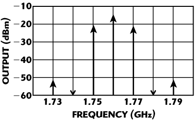
Figure 2 Simulated output spectrum of the harmonic generator.
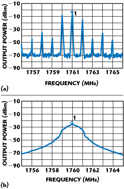
Figure 3 Measured output spectrum of the harmonic generator (a) two-tone signal and (b) CDMA IFA signal.
Figure 2 shows the simulated output of the harmonic generator after the transistor bias voltage was adjusted for two-tone signals. The simulation was performed with the ADS2003 software of Agilent Technologies. Figure 3 shows the second harmonic signal measurement results in the case of CW two-tone and CDMA 1FA signals. When the two figures are compared for the two-tone case, the simulation and measured results are practically similar, proving the validity of the harmonic generator.
The level of the second harmonic signals (2ω1, 2ω2, ω1+ω2) generated from the harmonic generator must be large enough to modulate the fundamental signal in the AM modulator. Variable gain amplifiers (VGA) are used to control the modulation factor.

Figure 4 Schematic of the proposed linearized power amplifier.
Figure 4 shows the schematic of the proposed linearized power amplifier. The predistortion IM generator uses vector modulators (VGA) to generate the in-phase and quadrature-phase components of the AM signals. VGA-3I, VGA-3Q and VGA-5I and VGA-5Q are controlling the in-phase and quadrature-phase components of the second and fourth harmonic signals. These signals modulate the fundamental signals. Finally, the vector modulator output generates the predistortion signals. This predistorter controls simultaneously the amplitude and phase of predistortion components using VGA amplitude variation. It provides faster adjustment of phase and amplitude than is provided by a conventional controller consisting of a variable phase shifter and a variable attenuator. The automatic level control (ALC) circuit at the input port stabilizes the device by maintaining a constant IM signal, in spite of variations in the incoming power level.
The fourth-order intermodulation signals (3ω1–ω2, 3ω2–ω1) can be generated by subtracting the second harmonic signals (2ω1, 2ω2), obtained from HG1, from the harmonic signals of HG2. To achieve independent control of the IM products of the power amplifier, the four VGAs control the second and fourth harmonic signals. The signals (2ω1, 2ω2, ω1+ω2) generated by HG1 under proper bias condition and the signals (3ω1-ω2, 3ω2-ω1) generated by adjusting variable attenuator A1 and phase shifter P1, modulate the fundamental signal in the AM modulator and the vector modulator output generates the predistortion signals. Then the four VGAs are used to control the amplitude and phase of the predistorted third and fifth IM signal independently.
The in-phase (I) and quadrature-phase (Q) components of the IM signals generated in the vector modulator are expressed as follows:
In-phase signals
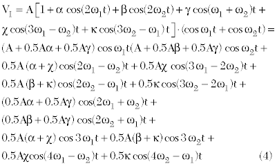
Quadrature-phase signals

where A = amplitude of CW two-tone
α = amplitude of 2ω1 signal among second harmonic signals
β = amplitude of 2ω2 signal among second harmonic signals
γ = amplitude of (ω1+ω2) signal among second harmonic signals
χ= amplitude of (3ω1-ω2) signal among fourth harmonic signals
Κ = amplitude of (3ω2-ω1) signal among fourth harmonic signals
The second- and fourth-order harmonic signals generated in the proposed harmonic generator are transferred to the predistortion IM3 and IM5 signals of the power amplifier to modulate the fundamental signals. By only changing the amplitude of the even harmonic signals, the phase and amplitude of the predistortion IM3 and IM5 components are controlled. Figure 5 shows that when the even harmonic signals are changed in amplitude by the modulation factor, the predistortion signals are changed in amplitude and phase simultaneously.
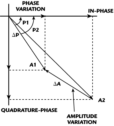
Figure 5 Amplitude and phase variations of the modulated signals.
Experimental Results
The linearizer was evaluated with a HPA made of a series connection of a Watkins Johnson AH1 and a Motorola MHL 9838 amplifier, for which the gain and P1dB are 43 dB and 37 dBm, respectively.
The signal components at 2ω1, 2ω2 and 3ω1–ω2, 3ω2–ω1 can be independently adjusted. Due to the fact that they are closely spaced to each other, they cannot be separated using a filtering technique. As a result, the signal components can be separated using an arithmetic operation. For optimal operation, HG1 is biased at 1.2 V and HG2 at 1.9 V. By adjusting the variable attenuator A1 and the phase shifter P1, the frequency components at 3ω1–ω2 and 3ω2–ω1 are extracted at the output of the combiner. The corresponding spectrum is shown in Figure 6. The input frequencies are 880 and 881 MHz with a frequency spacing of 1 MHz. The delay circuits are made of coaxial delay lines that are approximately 14.7 ns for Delay 1, 4.8 ns for Delay 2 and 2.2 ns for Delay 3.

Figure 6 Extraction of the 4th harmonic signals.
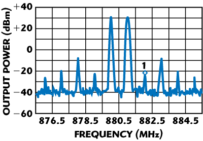
Figure 7 Two-tone test with cancellation of IMD3 only.
Figure 7 shows the measured IMD performance obtained by setting VGA-5I and VGA-5Q to minimum gain. In this case, it is observed that only the third-order IMD components are suppressed. The input frequencies are 880 and 881 MHz with a frequency spacing of 1 MHz and the output power is 30.7 dBm per tone. It shows that IMD3 is cancelled out by 27 dB.

Figure 8 Two-tone test with cancellation of IMD5 only.

Figure 9 Two-tone test with simultaneous cancellation of IMD3 and IMD5.
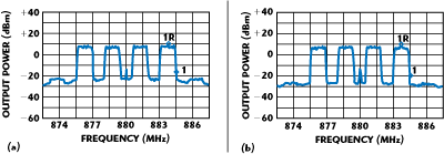
Figure 10 Output spectrum of the HPA at 24 dBm/FA (a) without linearizer and (b) with linearizer for IS-95 CDMA 4FA signals.
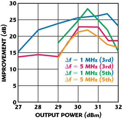
Figure 11 Improvements of IMD3 and IMD5 vs. output power for a two-tone signal.
As shown in Figure 8, the IMD5 components can be perfectly reduced while IMD3 is unchanged by setting VGA-3I and VGA-3Q to minimum gain and adjusting VGA-5I and VGA-5Q correctly. It shows that IMD5 is cancelled by 29 dB. Simultaneous suppression of IMD3 and IMD5 is shown in Figure 9. It can be seen that both IMD3 and IMD5 are cancelled by 25 dB. Figure 10 shows the IS-95 CDMA 4FA results. The test frequencies are 876.25, 878.75, 881.25, 883.75 MHz and the frequency bandwidth is 8.75 MHz. The test signal generator used is the ESG4433B from Agilent Technologies. Something like carrier leakage was observed for this equipment at the center frequency. Figure 11 shows the IMD3 and IMD5 improvements for an output power range from 27 to 32 dBm in the case of two-tone signals.
Conclusion
A novel amplifier linearization scheme, based on the even-order harmonic signals, has been proposed. The harmonic generator extracts the second and fourth harmonic signals and modulates the fundamental signal with the extracted harmonic signals with an AM modulator. Hence, the amplitude and phase of the predistortion signals are easily controlled simultaneously because the vector modulator consists of in-phase and quadrature-phase components, and its performance reduces the effort of retuning the attenuators and the phase shifters. In the experiments, simultaneous cancellation of IMD3 and IMD5 has been demonstrated with a reduction factor of more than 25 dB. Also, good IM cancellation characteristics are obtained for a wide dynamic range and different kinds of signals. If an adaptive controller is attached in the proposed linearizer, it is expected that the proposed predistortion method may be applied to many kinds of power amplifiers.
Acknowledgment
This paper was supported by the Research Fund, Kumoh National Institute of Technology, Gyungbuk, South Korea.
References
1. S.C. Cripps, RF Power Amplifiers for Wireless Communications, Artech House Inc., Norwood, MA, 1999.
2. P.B. Kenington, High-Linearity RF Amplifier Design, Artech House Inc., Norwood, MA, 2000.
3. T. Nesimouglu, D. Budimir, M.R. Moazzam and C.S. Aitchison, “Second Harmonic Injecting Technique for Low Intermodulation RF Microwave Amplifiers,” High Frequency Postgraduate Student Colloquium, September 1997, pp. 143-148.
4. C.S. Aitchison, M. Mbabele, M.R. Moazzam, D. Budimir and F. Ali, “Improvement of Third-order Intermodulation Product of RF and Microwave Amplifiers by Injection,” IEEE Transactions on Microwave Theory and Techniques, Vol. 49, No. 6, June 2001, pp. 1148-1154.
5. C.S. Aitchison, “The Current Status of RF and Microwave Amplifier Intermodulation Performance,” 2000 IEEE Radio Frequency Integrated Circuits Symposium Digest, pp. 113-116.
6. Y. Yang and B. Kim, “A New Linear Amplifier Using Low-frequency Second-order Intermodulation Component Feedforwarding,” IEEE Microwave and Guided Wave Letters, Vol. 9, No. 10, October 1999, pp. 419-421.
7. M.R. Mozzam and C.S. Aitchison, “A Low Third-order Intermodulation Amplifier with Harmonic Feedback Circuitry,” 1996 IEEE MTT-S International Microwave Symposium Digest, pp. 827-830.
8. D. Jing, W.S. Chan, S.M. Li and C.W. Li, “New Linearization Method Using Inter-stage Second Harmonic Enhancement,” IEEE Microwave and Guided Wave Letters, Vol. 8, No. 11, November 1998, pp. 402-404.
9. K. Horikawa and H. Ogawa, “Even-order Distortion Enveloping Method to Linearize Saturated High Power Amplifiers,” 1997 IEEE MTT-S International Microwave Symposium Digest, Vol. 1, pp. 79-80.
10. T. Kaho, Y. Nakasuga, H. Okazaki, K. Araki and K. Horikawa, “A Distortion Control Technique for Achieving High Power Efficiency in an HPA Array,” IEEE Transactions on Microwave Theory and Techniques, Vol. 50, No. 11, November 2002, pp. 2505-2512.
11. T. Kaho, T. Nakagawa, K. Araki and K. Horikawa, “Carrier Power to Intermodulation-distortion Power-ratio-Increasing Technique in Active Phased-array Antenna Systems,” IEEE Transactions on Microwave Theory and Techniques, Vol. 50, No. 12, December 2002, pp. 2987-2994.
12. H.S. Jang, Y. Kim, S.U. Kim, I.S. Chang and Y.C. Jeong, “Design of a New Predistorter Using Low Frequency Second-order Intermodulations of a Harmonic Generator,” 2002 Asia-Pacific Microwave Conference Proceedings, Vol. 1, pp. 149-152.
13. Y.C. Jeong, “A Design of Predistortion Linearizer Controlling the Individual Order of Intermodulation,” Thesis, Sogang University, South Korea, 1995.
14. Y. Kim, I.S. Chang and Y.C. Jeong, “An Analog Predistortion Linearizer Design,” Microwave Journal, Vo1. 48, No. 2, February 2005, pp. 118-126.
15. S.Y. Kim, M.A. Jang, K.K. Jeon, Y. Kim and Y.C. Jeong, “An Analog Linearizer Using Second Harmonic Signals Feedforwarding,” European Microwave Conference 2005, September 2005.
16. T.T. Ha, Solid-State Microwave Amplifier Design, John Wiley & Sons Inc., Hoboken, NJ, 1981.
