
The direct conversion (homodyne) transceiver architecture is gaining popularity. It allows more flexibility in a multi-band and multi-mode complex receiver system. It is a low cost solution, compared with the traditional heterodyne receiver, because the entire IF stage signal processing is eliminated. However, the problem of DC offset, poor IM2 and flicker noise impede the performance of direct conversion systems.
The root of the DC offset and poor IM2 problems is due to the fact that the RF signal and the LO are at the same frequency and the RF-to-LO isolation provided by the mixer is never infinite. The LO leakage finds its way into the RF path. It mixes with the LO signal itself to create a DC offset at the baseband. These problems can be greatly reduced by using a sub-harmonic mixer (SHM) topology. This article starts by briefly reviewing the standard Gilbert cell mixer. Next, four SHM topologies are discussed in detail. The article ends with a discussion of SHM enhancement techniques.
Traditionally, SHM is used for upper microwave and millimeter-wave ranges, where it is difficult to get frequency sources above 20 GHz. It is typically implemented with discrete anti-parallel diode pairs. Much research has been done to explore the possibility of using SHM for consumer radio transceivers such as WLAN and cell phones. This article targets the IC implementation of SHM in consumer markets.
Sub-harmonic Mixer Architecture
The standard single-balanced mixer (SBM) and double-balanced mixer (DBM) are well known and well documented.1 They are the foundation for sub-harmonic mixers (SHM). The IC implementations of the SBM and DBM are presented first. There are many ways to implement a mixer. The most widely used technique is to have the LO signal turn on and off the switch in the RF path. For SBM, the waveform for the LO can be modeled as a return-to-zero (RTZ) square waveform. The mixer output wave can be modeled as2

Equation 1 simply states that the RTZ square waveform consists of only odd harmonics of the LO. Upon mixing with the RF signal, it will create the upper and lower sidebands around the LO and its odd harmonics. Another observation is that the DC term in the bracket means that the RF signal is not suppressed. A typical SBM is shown in Figure 1. M1 is an RF buffer amplifier, while M2 and M3 provide the switching function needed for mixing action. Since M2 and M3 are not on at the same time, the output mixed signal is single ended, which matches the RTZ square model. A DBM fixes this problem by using a non-return-to-zero (NRTZ) square waveform. A typical DBM is shown in Figure 2. The LO simply changes/modulates the phase of the RF signal between 0° and 180°. The output is never grounded. The mixing result is modeled by2
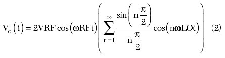
Equation 2 states that, in theory, by using the NRTZ switching waveform, the DC term in the equation is completely eliminated. Thus, the RF signal is greatly suppressed.
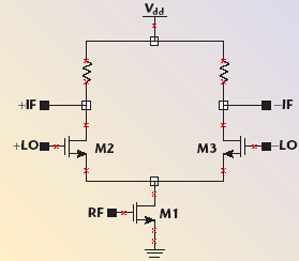
Fig. 1 Standard single-balanced mixer.
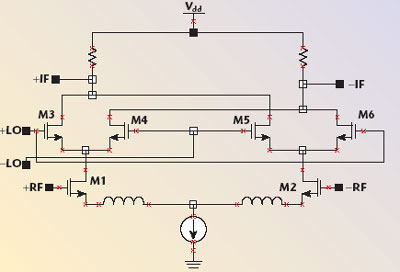
Fig. 2 Standard double-balanced mixer.
The modern SHM ICs are modified versions of SBM and DBM. They can be either single-balanced for low cost consideration or double-balanced for LO and RF carrier suppression. The first approach is based on a basic trigonometric equation
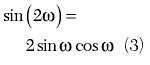
Equation 3 basically shows that, if the LO signal is phase-shifted by 90° and then multiplied by the original LO, twice the frequency of the LO is produced. This is exactly the property needed in a SHM. It is easily implemented by stacking another switching stage in the mixer. The non-balanced and single-balanced implementations of such a SHM are shown in Figures 3 and 4. For the non-balanced SHM, an RC network is used to create the 90° phase shift. It is then used to drive the two switching stages of the mixer. For the single-balanced SHM, a polyphase network is used to generate the 0° and 180°, 90° and 270° signal pairs. The double-balanced version is obtained by simply cross coupling two single-balanced SHMs. A similar implementation is demonstrated by S. Fang, et al.4

Fig. 3 Single-ended stacked sub-harmonic mixer.
The second generalized approach is based on yet another simple equation
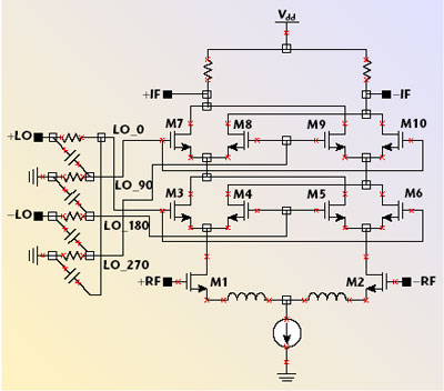
Fig. 4 Single-balanced stacked sub-harmonic mixer.
The absolute function flips the negative cycle of the LO to positive. The positive cycle of the LO stays the same. Thus, the frequency of the signal is doubled. Compared with the first approach, it is a less graceful way to create a harmonic. This implementation will have more and stronger undesired harmonic signals, in addition to the desired one. Such single- and double-balanced SHMs are shown in Figures 5 and 6, respectively. The bottom two-transistor pairs in the single-balanced SHM have their collectors tied together to match the absolute function. The upper half is exactly the same as for the standard SBM. The double-balanced version of such a SHM is simply the extension of the DBM circuit.

Fig. 5 Single-balanced sub-harmonic mixer.

Fig. 6 Double-balanced sub-harmonic mixer.
The third way to implement a SHM is based on the technique called anti-parallel diode pair (APDP). The active circuit can be expressed as a polynomial. The unique property of an APDP is that its polynomial only has odd-order terms. The even harmonics are suppressed. With the correct bias, each diode is turned on 25 percent of the time, and the odd-order-only polynomial is closely simulated. Since high quality diodes are hard to come by in low cost CMOS, many attempts have been made to use transistor-based limiters to replace the APDP. Many implementations have been demonstrated.7 However, the architecture suffers from poor LO leakage. As long as high quality diodes are not available, the other two SHB architectures have superior RF performance.
Enhancement Techniques
To design a better SHM, many techniques used in standard mixer design can be adopted. For example, in the stacked single-balanced SHM, there are four stacks of transistors (counting the biasing transistor as one stack) in order to implement Equation 3. As the power supply requirements continue to drop lower and lower, the signal swing level is severely hampered. One technique that helps this situation is the current folded mixer.9 Instead of stacking each transistor pair vertically, they are arranged horizontally with the proper bias scheme. The tradeoff, however, is complexity, high power consumption and potentially higher cost.
Linearity can be improved using the Multi-Tanh technique pioneered by Barrie Gilbert. For the standard DBM, two more scaled transistors are added to the input transistor pair. The scaled version transistors are cross-coupled with the original input transistor pair.3 The scaling factor A needs to be carefully selected. By analogy, it is similar to a multi-resonator filter design. Each individual resonator is offset from the operating frequency. By coupling the resonator correctly, the bandwidth of the filter can be increased at the expense of the notch depth. In the Multi-Tanh Gilbert cell, the input gain is reduced by 4A/(1 + A)2.8 It flattens the transconductance Gm of the gain stage. Thus, the linearity is greatly improved. A rule of thumb number for A is approximately 4.
In the SHM design, it is very critical to have a precise 90° phase shift. The generic SHM presented so far utilized one stage of an RC polyphase filter. All the RC constants correspond to one cutoff frequency, which is sufficient for narrowband operation. For broadband operation, a multiple stage polyphase filter can be added. Each stage of the polyphase filter should be offset from the center of the operating band. With simulation, proper frequency offsets can be determined to ensure a precise phase shift over a broad operating frequency range.
The RF-to-LO port isolation can be further improved in SHM systems by using a cascode input stage. Again, using the standard SHM, the input CE stage can be replaced with a standard CE-CB cascode input gain stage. In a SHM implementation, however, a five-level stack of transistor pairs is required for each mixer cell. The current folding technique comes in handy in this situation.
For the most demanding transceiver system, the reader may envision a super performance mixer with an SHM architecture to reduce the DC offset in an homodyne transceiver, with Multi-Tanh and cascode techniques to improve linearity, with a multistage polyphase filter to increase the operating bandwidth, and finally a current folding technique to increase headroom. For a low cost, less demanding system, a simple single-balanced mixer IC can be adopted.
Conclusion
In summary, there are many tradeoffs involved in the SHM design, just like for the rest of the RF system. With such a wide range of RF transceivers on the market, one mixer topology can hardly fit all. It is the designer’s responsibility to identify the correct topology on a case-by-case basis. This will ensure a good RF performance for the lowest power consumption and the lowest cost for the specific application.
References
1. B. Razavi, RF Microelectronics, Prentice-Hall, Upper Saddle River, NJ, 1998.
2. H.L. Krauss, C.W. Bostian and F.H. Raab, Solid State Radio Engineering, John Wiley & Sons Inc., Hoboken, NJ, 1980.
3. L. Sheng, J.C. Jensen and L.E. Larson, “A Wide-bandwidth Si/SiGe HBT Direct Conversion Sub-harmonic Mixer/Downconverter,” IEEE Journal of Solid State Circuits, Vol. 35, No. 9, September 2000, pp. 1329–1337.
4. S. Fang, S. Lee, D. Allstot and A. Bellaouar, “A 2 GHz CMOS Even Harmonic Mixer for Direct Conversion Receivers,” 2000 International Symposium on Circuits and Systems Digest, pp. 807–810.
5. M. Huang, S. Lee and C. Kuo, “A CMOS Even Harmonic Mixer with Current Reuse for Low Power Applications,” 2004 International Symposium on Low Power Electronic and Design Digest, pp. 290–295.
6. K. Nimmagadda and G. Rebeiz, “A 1.9 GHz Double-balanced Sub-harmonic Mixer for Direct Conversion Receivers,” 2001 IEEE Radio Frequency Integrated Circuits Symposium Digest, pp. 253–258.
7. T. Yamaji and H. Tanimoto, “A 2 GHz Balanced Harmonic Mixer for Direct-conversion Receivers,” 1997 IEEE Custom IC Conference, pp. 193–196.
8. A. Podell, RFIC Design and Applications, Besser Associates Short Course.
9. E. Tiiliharju and K Halonen, “A Direct-conversion BICMOS Mixer for GHz Applications,” The 8th Electronics, Circuits and Systems Conference Digest, Vol. 3, 2001, pp. 1599–1602.
Louis Fan Fei received his BEE and MSEE degrees from Georgia Tech in 1996 and 1998, respectively. He worked on WLAN and wireless local loop circuits at Lucent/Agere Systems from 1998 to 2003. He is currently an RF engineer at Garmin International, where he designs GPS receivers. He has written more than 10 technical papers for Microwaves and RF, RF Design and Applied Microwave and Wireless.