
The quest for a low-noise, high-switching-speed synthesizer has become a common trend in modern wireless systems. A large division ratio is required for the feedback path of a conventional phase-locked loop (PLL) if microwave frequencies need to be synthesized. To mitigate the problem, an offset PLL architecture is often used, which includes a mixer in the feedback path. The output signal from a voltage-controlled oscillator (VCO) is down-converted to a much lower frequency by mixing it with an externally generated offset frequency signal. A wide tuning range, often required in microwave bands, dictates the use of a pseudo-coherent multi-VCO configuration.1 A single-VCO 10 GHz offset PLL architecture, intended for point-to-point radio applications, has also been reported.2 On the other hand, a relatively high reference frequency is usually required to obtain similar performance using a conventional PLL.3
Microwave Frequency Synthesis
A simplified offset PLL configuration for microwave frequency synthesis is shown in Figure 1. The VCO output signal Foutput is first divided by a fixed ratio prescaler, having a division ratio K (where K is an integer). The output signal from the prescaler drives an input port of the mixer. An externally generated signal Foffset drives the other input (LO port) of the mixer. The resulting low-frequency mixing product is filtered by a low pass filter (LPF) and applied to the main divider, having a division ratio N (where N is generally a variable of real or integer type). A phase detector (PD) compares phase of the feedback signal (from the output of the main divider) with the phase of an externally generated reference signal Freference. The resulting error signal is applied, through the loop filter F(s), to the control input of the VCO. Optionally, depending on the technology used, the mixer could be driven directly from the VCO output (in such case the fixed prescaler is omitted).
Self-offset PLL
The self-offset PLL configuration, proposed here, is shown in Figure 2. Two input signals for the mixer are generated internally within the same PLL, thus the separate offset frequency source is not required. Two independent prescalers (having division ratios K and L, respectively) divide the VCO output frequency to generate the two input signals required for down-conversion mixing. Preferably, the LO port of the mixer is being driven by the prescaler with the larger division ratio L. The difference between the division ratios of the two fixed prescalers is defined as an integer value x such that

The frequency of the down-converted signal (at the output of the low pass filter), can be expressed by

Substituting L from Equation 1 into Equation 2 yields

Therefore, the tuning range “seen” by the main divider is reduced by the factor of

The frequency of the signal at the phase detector’s feedback input (at the output of the main divider) can be expressed by

Substituting Equation 4 into Equation 6 yields

For the case of a conventional phase-locked loop, having only a divide by K prescaler and a main divider in the feedback path, the frequency of the signal at the phase detector’s feedback input is given as

where Nconv represents the division ratio for the main divider of the conventional PLL.
Assuming identical comparison frequencies for the self-offset and conventional phase-locked loops yields

The reduction in the division ratio of the main divider (when comparing the self-offset PLL with the conventional phase-locked loop) can be calculated by further simplifying Equation 10 such that

The phase noise improvement inside the PLL loop bandwidth, resulting from that reduction, can be estimated by 20 log (N/Nconv). Figure 3 shows the phase noise improvement (in dB) as a function of x, with K as a parameter.

The choice of a low value of x and a large value of K gives the largest improvement of the phase noise in dB. Increasing the value of K beyond 10 results in smaller incremental improvements than when varying the value of K from 1 to 10.
As in any conversion scheme involving a mixer, spurious mixing products have to be considered and mitigated. This restricts the choice of the x and K values combination. Mixing products that fall exactly into the frequency band of the desired output are difficult to mitigate. It is therefore important to avoid values of x and K which would result in their generation, as can be described by Equations 13a or b:

where m, n are the harmonic indexes
Substituting Equation 4 into Equations 13a and b yields

From Equations 14a and b

Then,

which gives


thus

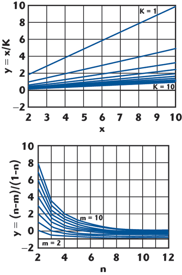
In most cases the x value will be chosen to be much smaller than the K value. Therefore, Equation 19a will be considered here as a design guide and is graphically represented in Figure 4. The right- and left-hand sides of Equation 19a are displayed side by side (the y axis has exactly the same scale on both graphs). Combinations of x, K, which give the same y axis value as any combination of harmonic indexes m, n, are to be avoided. For practical circuits it is not always possible to avoid all spurious products; therefore, some compromise solution has to be pursued. When the division ratio K is made to be a large integer number (in order to maximize the phase noise improvement), mixing can be done using “all digital” implementation, as shown in Figure 5. A D-type flip-flop can be used to produce the mixing product of two signals, driving its D and CLK (clock) inputs. An analog mixer can therefore be replaced with a “digital mixer”.4
From Equation 1

The frequency of the mixing product, delivered by the Q output, can be expressed either as


where
FQ = frequency of the signal at Q output
FCLK = frequency of the signal driving CLK input
M = 1,2,3,…
FD = frequency of the signal driving D input on condition that FD is constrained as

or expressed as

on condition that FD is constrained as

Thus, there are two modes of digital mixer operation: a sideband non-inverting mixing mode and a sideband inverting mixing mode. In order to maintain only one mode of mixing, the frequency of the signal driving the D input has to be constrained. As a result, the choice of K and x values combination is further restricted. As an example, the case of non-inverting mixing will be analyzed here. Equation 21 can be written as

Therefore, the tuning range seen by the main divider is, in this case, reduced by the factor of

The reduction in the division ratio of the main divider (when comparing a self-offset PLL including a digital mixer with a conventional phase-locked loop) can now be derived as well. Assuming identical comparison frequencies for the digital self-offset and conventional phase-locked loops yields

It is easy to see that Equation 28 is equivalent to Equation 5 and Equation 32 is equivalent to Equation 12 when M = 1. Furthermore, Equation 22 can be written as

which gives


from which it can be concluded that

Thus, in order to maintain only one mode (of non-inverting mixing), the choice of K and x values has to be restricted, as described by Equation 37.
Experimental Results
The concept of a self-offset PLL has been experimentally verified for the case that utilizes an analog mixer. The prototype included an HMC510 MMIC VCO from Hittite Microwave Corp. (9 GHz push-push type HBT VCO), which has two additional outputs: a half-frequency and divide-by-four. The half-frequency output was further divided by a divide-by-three prescaler HMC437 (from Hittite Microwave Corp.), while the divide-by-four output was further divided by a divide-by-two prescaler HMC364 (also from Hittite Microwave Corp.). Thus, the combination of K = 6 and x = 2 was used for this prototype arrangement.
In order to synthesize the output frequencies from 8.151 to 8.851 GHz, with the comparison frequency set to 100 MHz, division ratios for the main divider shall cover a range between 3.39625 and 3.6879167. To obtain such small division ratios, an AD9858 direct digital synthesizer (from Analog Devices Inc.) was used as a fractional-N main divider. The AD9858 DDS was particularly convenient to use, due to its fine frequency resolution and its level of integration. The AD9858 includes an analog (Gilbert cell type) mixer and a 150 MHz phase-frequency detector. The drawback is that the noise floors of the DDS and phase-frequency detector limit the achievable close-in noise pedestal at the PLL output. Other drawbacks are the spurious signals at the DDS output (inherent in DDS). Therefore, a lower than maximum achievable PLL closed-loop bandwidth has to be set in order to mitigate the problem.

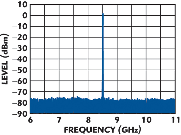
The measured output spectrum of the prototype self-offset PLL (in the vicinity of 8.502 GHz) is shown in Figure 6. Close-in spurious are at least –44 dBc (below carrier) and, further away, at least –77 dBc, as shown in Figure 7. Figure 8 shows the measured closed-loop response. The loop bandwidth was set to 350 kHz. The phase noise of the prototype self-offset PLL (in the vicinity of the top of the tuning range) is shown in Figure 9.
Conclusion
A new class of phase-locked loop, the self-offset PLL, has been proposed and experimentally verified. The new configuration permits a large reduction in the division ratio of the main divider (when comparing the self-offset PLL with a conventional phase-locked loop), resulting in an increased open-loop gain and the possibility for fast settling and significant improvement of the phase noise inside the PLL loop bandwith. Two variants (utilizing either analog mixing or digital mixing) were discussed. From a theoretical study, simple design guidelines were derived for each of the two variants.

References
1. D. Pedreira, J.I. Alonso, F. Perez and C. Briso-Rodriguez, “High Performance Offset Synthesizer,” Proceedings of the 35th European Microwave Conference, Paris, France, 2005, pp. 225–228.
2. M. Piloni, A.G. Milani and M. Baggioli, “A New Millimeter-wave Synthesizer for Point-to-point Radio Supporting High Data Rates Using Complex Modulation Formats,” Proceedings of the 35th European Microwave Conference, Paris, France, 2005, pp. 229–232.
3. Y.J. Lee, S.B. Hyun, G.Y. Tak and H.K. Yu, “Fast Settling 9 GHz PLL Using 528 MHz Reference PLL Clock for MB-OFDM UWB System,” Proceedings of the 1st European Microwave Integrated Circuits Conference, Manchester, England, 2006, pp. 179–182.
4. J. Turczynski, R. Maksymowicz, B. Malec and J. Ponikiewski, “Wybrane Uklady z Techniki Cyfrowej,” WKiL, Warsaw, Poland, 1983, pp. 81–86.
Bogdan Sadowski received his MS degree from the Warsaw University of Technology (formerly Warsaw Technical University), Warsaw, Poland, in 1985. He is currently a senior RF engineer with Harris Stratex Networks Inc. (formerly the Microwave Communications Division of Harris Corp.). His interests include frequency synthesis and nonlinear circuits.