
Along with monopole, patch and slot antennas, the inverted-F antenna (IFA) has become of primary importance for portable and handheld wireless communication units. It is known as a high-efficiency, quasi-omni-directional antenna, with a height of approximately 0.05 to 0.1λ, which is 2.5 to 5 times shorter than a quarter-wave monopole.1–4 The wire or planar inverted-F antenna (PIFA) is a low-profile modification of the quarter-wave monopole, and thus belongs to the group of unbalanced antennas.
The demand for smaller communication devices for personal communication systems has led to a constant search for methods to reduce cellular phone dimensions. However, the wavelength does not decrease at the same rate as the size of the mobile phone, due to the higher frequency band used. Even a quarter-wavelength antenna, such as the PIFA, tends to become large for a cellular phone.
In this article, a novel PIFA structure, with inserted Yagi-type arrayed-slots and using a large offset rectangular L-shaped feed line is described, which has similar radiation pattern properties, but with the advantage of being multi-band compared to a conventional PIFA.2,4–6

The proposed antenna has a lower profile and a smaller size than a conventional PIFA.1–6 This article also describes the simulated and measured results for multi-band performance and experimental gain and the radiation patterns.
Antenna Structure and Design Parameters
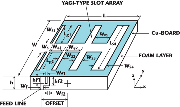
The structure of the proposed antenna is shown in Figure 1. It consists of a metallic plate on a foam substrate, with a Yagi-type array of etched slots and a large offset U-L-shaped feed line. A rectangular L-shaped microstrip feed line is proposed to match the input impedance of the antenna.
A large offset U-L-shaped feed line is used to extend the bandwidth proportionally to the slot width. The feeding structure of the proposed antenna leads to an impedance matching over a wide frequency band and is better than the conventional feed line structures. The proposed antenna can easily be constructed at low cost and has a low antenna height above the ground plane of the system circuit board.
The inserted Yagi-type etched-slot array on the patch element acts as multi-band resonant elements of the antenna. The width of each slot was etched to a different size, but the length of the slots was kept the same.

Ls1 is the length of the slots, Ws1 is the width of the first slot, Ws2 is the width of the second slot, Ws3 is the width of the third slot, Ws4 is the width of the fourth slot, Wg1 is the gap between the first and second slots, Wg2 is the gap between the second and third slots, Wg3 is the gap between the third and fourth slots, Wf is the width of the feed line, Wf1 and hf1 are the width and height of the etched internal part of the U-shaped feed line, and Wf2 and hf2 are the width and height of the right part of the U-shaped feed line.
The optimized antenna dimensions are: Ws1 = Ws2 = 1 mm, Ws3 = 3 mm, Ws4 = 5 mm, Lg1 = 8 mm, Ls4 = 20 mm, Ws4 = 5 mm, Wg1 = 8 mm, Wg2 = 9 mm, Wg3 = 8 mm, Wf = 3.0 mm, Wf1 = 1.1 mm, Wf2 = 2 mm, hf1 = 4.5 mm, hf2= 6 mm, offset = 13 mm. The antenna characteristics are sensitive to the design parameters (Ls1, Ws3, Ws4, Ls4, Wf, Wf1, Wf2, hf1, hf2) and depend highly on the offset.
Simulation and Experimental Results
The proposed antenna was designed using the commercial program CST Microwave Studio.7 The antenna was fabricated using a Cu-board and foam layer (h = 1.0 mm) with overall dimensions of 37 x 25 x 7.5 mm. The antenna measurements were made with an HP8510B network analyzer. Figure 2 shows a comparison of the simulated and measured return loss of the proposed antenna.
The experimental impedance bandwidth is approximately 825 to 998 MHz (20 percent at the 865 MHz center frequency) and 1703 to 2112 MHz (21.5 percent at the 1900 MHz center frequency) for an S11 less than –10 dB, and covers the cellular, PCS, IMT-2000 and WLL bands. After calibration using a horn antenna, the radiation patterns in the far field were measured.
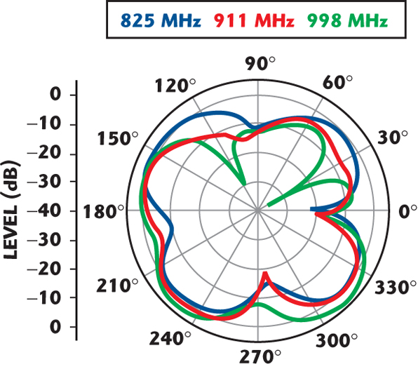
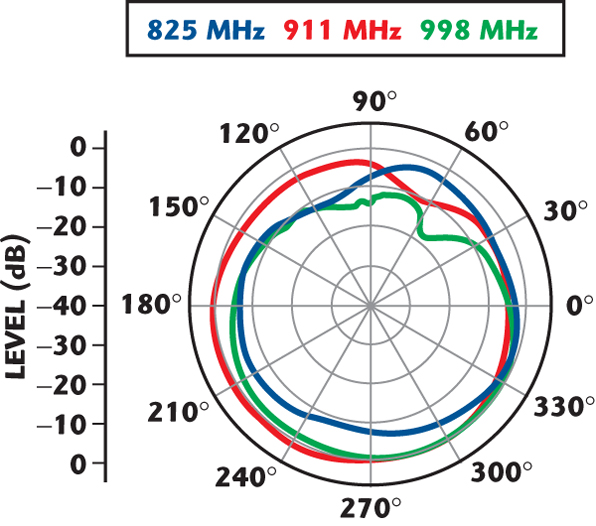
The measured radiation patterns in the x-y plane for the proposed antenna at 825, 911 and 998 MHz are shown in Figure 3. The measured radiation patterns in the y-z plane for the proposed antenna at the lower band are shown in Figure 4. The measured radiation patterns in the x-z plane for the proposed antenna at the lower band are shown in Figure 5.
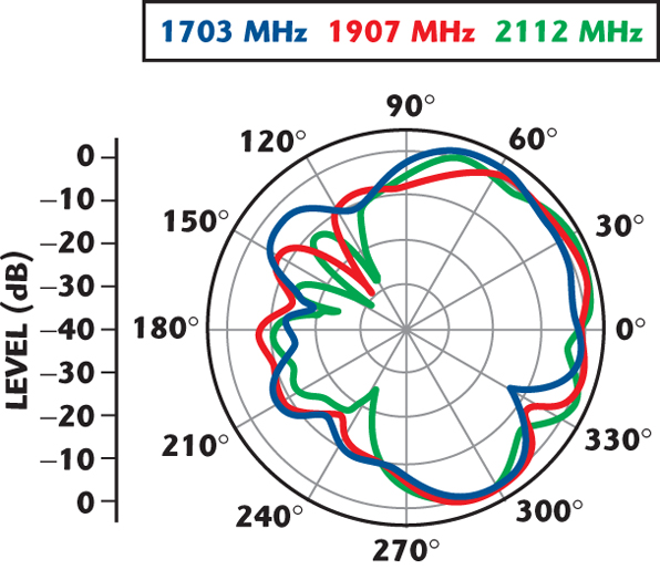
In the higher band, the measured radiation patterns in the x-y, y-z and x-z planes for the proposed antenna are also shown in Figures 6, 7 and 8, respectively. The radiation patterns at these operating bands are similar to those of a simple microstrip patch antenna. The radiation characteristics of the proposed antenna are seen to have asymmetric characteristics. This is due to the basic characteristics of a planar structure. However, no prominent difference between the radiation patterns at these operating bands are seen. This suggests that the radiations are stable in the operating band for PCS, IMT-2000 and WLL operations.
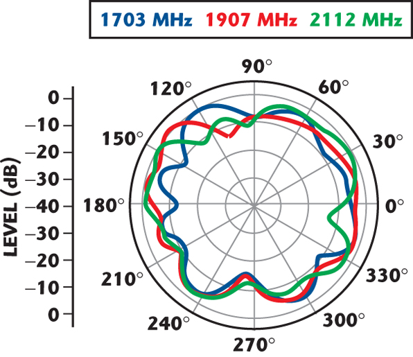
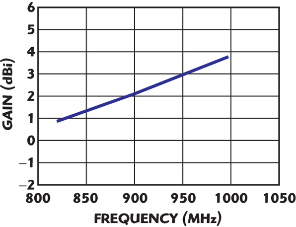
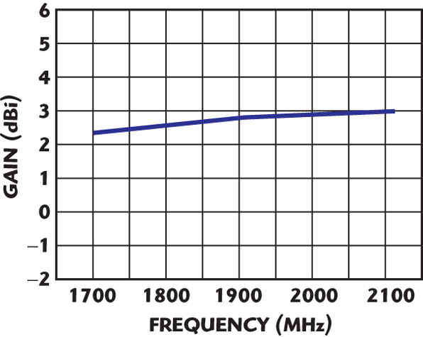
Figure 9 shows the measured antenna gain for operating frequencies across the lower band (cellular and GSM). Figure 10 shows the measured antenna gain for operating frequencies across the higher band (PCS, IMT-2000 and WLL). The peak antenna gain is approximately 3.6 and 2.6 dBi for the lower (cellular, GSM) and the higher (DCS, PCS, IMT-2000, WLL) operations, respectively.
Conclusion
In this article, a novel PIFA antenna structure is described, consisting of an inserted Yagi-type array of slots and using a large offset U-shaped feed for cellular, PCS and IMT-2000 operations.

The proposed antenna can easily be constructed at low cost, and has a low antenna height above the ground plane of the system circuit board. In this case, a large offset U-shaped feed leads to good impedance matching over a wide frequency band.
The inserted Yagi-type slot-array on the patch element acts as a multi-band resonant element at the usable frequencies. The experimental impedance bandwidths are approximately 825 to 998 MHz (20 percent bandwidth) and 1703 to 2112 MHz (21.5 percent bandwidth) for an S11 less than –10 dB, covering the cellular, PCS and IMT-2000 operations for mobile communications. Good radiation characteristics have also been observed.
References
1. R.J.G. Guertler, “Isotropic Transmission-line Antenna and Its Toroid-pattern Modification,” IEEE Transactions on Antennas and Propagation, Vol. 25, 1977, pp. 386–392.
2. K. Fujimoto, A. Henderson, K. Hirasawa and J.R. James, Small Antenna, Research Studies Press, Hertfordshire, UK, 1987.
3. H.C. Go and Y.W. Jang, “Characteristic Analysis of a Low Profile Post-type Monopole Antenna with Dual Plate,” Microwave Journal, Vol. 48, No. 5, May 2005, pp. 260–264.
4. C.R. Rowell and R.D. Murch, “A Capacitively Loaded PIFA for Compact Mobile Telephone,” IEEE Transactions on Antennas and Propagation, Vol. 45, No. 5, May 1997, pp. 837–842.
5. S.L. Chien, F.R. Hsiao, Y.C. Lin and K.L. Wong, “Planar Inverted-F Antenna with a Hollow Shorting Cylinder for Mobile Phone with an Embedded Camera,” Microwave and Optical Technology Letters, Vol. 41, No. 5, June 2005, pp. 418–419.
6. Z.D. Liu, P.S. Hall and D. Wake, “Dual-frequency Planar Inverted-F Antenna,” IEEE Transactions on Microwave Theory and Techniques, Vol. 45, No. 10, October 1979, pp. 1451–1457.
7. CST Microwave Studio 5.0, CST Ltd.