
The investigation of the use of ultra-wideband (UWB) has been one of the most controversial technologies of modern times. Its applications can be seen in diverse areas such as local area networks, position location searching, advanced imaging of the human body, etc. Microwave ring resonators are the components proposed for filtering, modulation and multiplexing/demultiplexing tasks in UWB integrated circuits. The basic concept for the microwave ring resonator was first proposed by P. Troughton in 1969.1 It was used in the measurement of the phase velocity and dispersive characteristics of a microstrip line. A further study on microwave ring resonators, using transmission-line models, was proposed.2 This model provided a T-network equivalent circuit to analyze the ring resonator structure. It has been proven that the microwave ring resonator can support two degenerate modes and offers bandpass characteristics. There have been many studies of dual-mode ring resonator bandpass filters.3–5 However, these filters have narrow band characteristics and high insertion loss because of the coupling gap effect. L.H. Hsieh and K. Chang have proposed a ring resonator bandpass filter.6 This filter provides a wide passband, sharp rejection and low insertion loss, but a spurious response is excited at 2f0. Also, the addition of two tuning stubs results in enlarging the area of the overall filter structure.
The idea presented in this article is based on a ring resonator structure, with the addition of stepped-impedance stubs and tapped input/output (I/O) lines, to construct a high performance bandpass filter. The tapped I/O lines may have an independent extra transmission zero in the stop-band without requiring complex coupling between resonators.7,8 Without altering the passband response, the tapped I/O line can be properly applied to both feeding ports in order to control the positions of the extra zero. This is a very useful feature in practical receivers for rejecting spurious response and enhancing the rejection level in the stop-band of a bandpass filter. The proposed structure can suppress the spurious passband and save more area of the overall filter structure without degrading the performance of the bandpass filter.
Stepped-impedance Open Stubs
The band-stop circuits, illustrated in Figure 1, are designed to excite a band-stop response by adding two l/4 open stubs on two sides (0° and 90°) of the ring resonator. Based on transmission line theory, a transmission line section having a length (bl < π/2) can be replaced by combining a short length (bl < π/4) of line of high characteristic impedance with a short length (bl < π/4) of line of low characteristic impedance. The latter can be referred to as a stepped-impedance structure. The EM simulated electric current distributions in the ring circuit and in a stepped-impedance open stub band-stop filter at the same fundamental resonant frequency are shown in Figure 2. The simulated electric current shows that the minimum electric fields appear at positions A and B, which correspond to the maximum magnetic fields. Thus, both circuits provide band-stop characteristics by presenting a virtual ground at their outputs at the resonant frequency, as can be observed in their simulated insertion loss frequency responses, shown in Figure 3. Additionally, the stubs can be easily implemented inside the ring resonator because their length ls must be shorter than l/8. A new filter is formed which can provide a more compact size.

Fig. 1 Band-stop circuits; (a) an open stub and (b) a stepped-impedance stub.

Fig. 2 Simulated electric current at the resonant frequency for (a) a ring resonator and (b) a stepped-impedance stub.

Fig. 3 Simulated insertion loss of the band-stop filters.
Figures 4 and 5 show the tapped-line structure and its corresponding transmission line model. The position parameters of the tapped line can be obtained from9
where
lt = position of tapped-line point
Z1 = impedance of the tapped line
Qs = loaded quality factor
Z0 = characteristic impedance of the transmission line

Fig. 4 Tapped-line resonator.

Fig. 5 Tapped-line resonator equivalent circuit.
UWB Filter Using Dual-mode Ring Resonator with Spurious Passband Suppression
A novel bandpass microstrip filter based on a ring resonator with tapped I/O lines is shown in Figure 6. The input and output ports are directly connected to the ring resonator at 180° and 270°. Two stepped-impedance tuning stubs are implemented within the resonator at 0° and 90°. The circumference lr of the ring resonator is given by Equation 3, where n is the mode number, λg is the guided wavelength and a perturbation is positioned at 45°

Fig. 6 Layout of the designed UWB filter.
The ring resonator and λ/8 stepped-impedance stubs are designed to resonate at 4.5 GHz and fabricated on an RT/Duroid 6010.2 substrate with a thickness h = 25 mil and a relative dielectric constant εr = 0.2. The dimensions of the filter are lr = 31.4 mm, a = 0.3 mm, b = 1.8 mm, c = 3.3 mm, d = 1 mm, e = 0.3 mm, f = 0.3 mm, g = 3.2 mm, l = 3.5 mm, i = 1.9 mm, j = 0.6 mm, p = 7 mm and the width of perturbed square stub is w = 0.5 mm. The total size of the filter is less than 20 x 20 mm; a photograph of the prototype filter is shown in Figure 7. The passband and stop-band responses of the designed bandpass filter are shown in Figures 8 and 9. The perturbation stubs can generate two transmission zeros or dual modes on both sides of the passband, located within 2.7 and 3.02 and 6.01 and 6.4 GHz. The filter has a 3 dB fractional bandwidth of 60 percent, an insertion loss less than 0.8 dB, two rejection bands greater than 18 dB within 2.46 to 3.22 GHz and 5.79 to 12 GHz, and attenuation rates for the sharp cutoff frequency responses of 177.7 dB/GHz at the lower edge of the passband and 181.8 dB/GHz at the higher edge. As shown, the spurious response of the designed filter can be considered as effectively suppressed. The rejection of the spurious response from 7 to 11.5 GHz is successfully suppressed to a level less than –18 dB by the effect of the tapped I/O lines. The edge of the transmission passband is related to the length c of the stepped-impedance stub, as shown in Figure 10. The bandwidth and the center frequency of the proposed filter can be easily tuned over a 700 MHz range by adjusting the length of c.
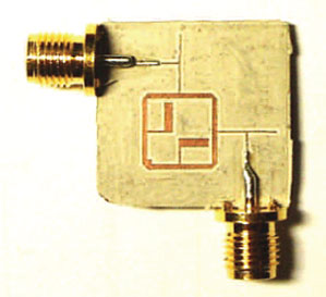
Fig. 7 The fabricated UWB bandpass filter.

Fig. 8 Passband performance of the designed UWB filter.

Fig. 9 Spurious response of the designed bandpass filter.
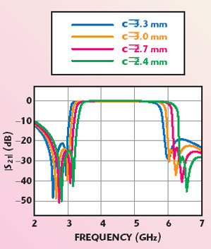
Fig. 10 Simulated performance of the passband UWB filter as a function of the length c.
The measured performance shows good agreement with the simulated results. The slight difference between the simulated and measured results may be due to a fabrication error, which can be improved by more precise fabrication technology.
Conclusion
This article presents a wideband microstrip bandpass filter with tapped I/O lines. Numerical simulations, using Zeland-IE3D, show good agreement with experiments. The proposed microstrip bandpass filter has the advantage of high performance, providing wider and deeper stop-band characteristics. The measured data for the fabricated bandpass filter also shows a fairly good insertion loss of approximately 0.7 dB. It can be integrated in an UWB radio system.
References
1. K. Chang and H.C. Hsieh, Microwave Ring Circuits and Related Structures, Second Edition, Wiley, New York, NY, 2004.
2. K. Chang, T.S. Martin, F. Wang and J.L. Klein, “On the Study of Microstrip Ring and Varactor-tuned Circuits,” IEEE Transactions on Microwave Theory and Techniques, Vol. 35, December 1987, pp. 1288–1295.
3. J.S. Hong and M.J. Lancaster, “Bandpass Characteristics of New Dual-mode Microstrip Square Loop Resonators,” Electronics Letters, Vol. 31, No. 11, May 1995, pp. 891–892.
4. J.S. Hong and M.J. Lancaster, “Microstrip Bandpass Filter Using Degenerate Modes of a Novel Meander Loop Resonator,” IEEE Microwave and Guided Wave Letters, Vol. 5, November 1995, pp. 371–372.
5. J.A. Curtis and S.J. Fiedziuszko “Miniature Dual-mode Microstrip Filters,” 1991 IEEE MTT-S International Microwave Symposium Digest, Vol. III, pp. 443–446.
6. L.H. Hsieh and K. Chang, “Compact, Low Insertion-loss, Sharp-rejection and Wide-band Microstrip Bandpass Filters, Part 1,” IEEE Transactions on Microwave Theory and Techniques, Vol. 51, No. 4, April 2003, pp. 1241–1246.
7. M. Matsuo, H. Yabuki and M. Makimoto, “The Design of a Half-wavelength Resonator BPF with Attenuation Poles at Desired Frequencies,” 2000 IEEE MTT-S International Microwave Symposium Digest, Vol. II, pp. 1181–1184.
8. K. Wada and I. Awai, “Heuristic Models of Half-wavelength Resonator Bandpass Filter with Attenuation Poles,” Electronics Letters, Vol. 35, 1999, pp. 401–402.
9. C.Y. Ho and J.H. Weidman, “Improved Design of Parallel Coupled Line Filters with Tapped Input/Output,” Microwave Journal, Vol. 26, No. 10, October 1983, pp. 127–130.