

RF application engineers and component designers throughout the world are constantly striving to find fast and accurate design tools to enable them to reduce design cycles and speed up the development process, and thus minimize customer return times.
As design engineers’ needs advance, so too must the software that they use and rely on. It is vital that software developers keep ahead of the game and improve on every new release. Mician’s latest version of the μWave Wizard™ CAD tool, version 6.5, demonstrates that fact.
Before examining the specifics of the new version consider the general attributes of the μWave Wizard. It is a CAD tool for the design of passive microwave systems and components based on the well-known fast and accurate mode matching (MM) method. This technique is particularly suitable for fast simulation and optimization of many kinds of waveguide components, including combline and dielectric resonator filters and horn antennas, as well as entire antenna feed networks.
The mode matching method and its derivatives such as the hybrid boundary contour mode matching (BCMM) method and the 2D finite element/mode matching are the only techniques capable of offering fast processing speed with very high accuracy.
The secret for achieving very high speed is to avoid the use of time-consuming full 3D solvers wherever possible and to apply the MM method and its derivatives instead. This should even be the case for structures that at first glance seem to be suited for 3D solvers only, like combline resonators, OMTs and turnstile junctions, and radiation into free space out of arbitrary apertures.
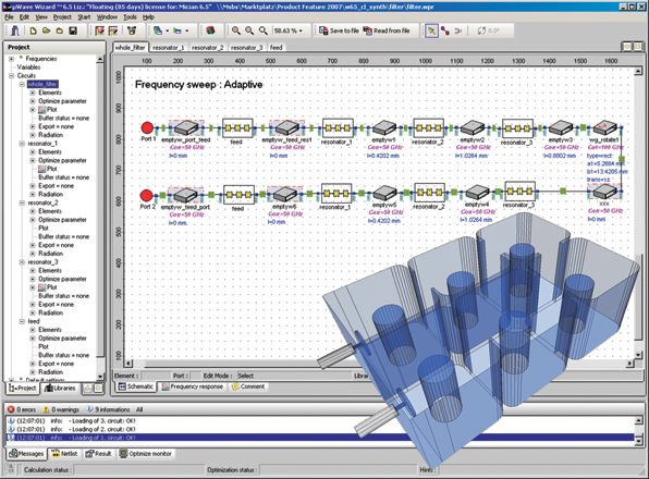
The basic idea behind the CAD tool is to break down the entire structure into smaller functional segments by using hierarchical sub-circuits containing smaller elements such as steps, irises, cavities, obstacles and empty waveguide connections, as shown in Figure 1.

Several element libraries containing more than 250 pre-designed elements for every design purpose are offered. These elements can be placed and connected in a schematic as in a circuit simulator and the properties such as geometries and materials can easily be assigned to each of those elements. Recently, a 3D FEM solver has been integrated for structures with very complex geometries or with features not feasible to be implemented in MM. For full flexibility, some elements also allow the import of user defined geometries from external data files (STL-files, for example).
Usually the integrated 3D solver is only being used for small segments (single elements) of the structure and has a multi-modal full-wave interface to all other parts of the structure. The result is a speeding up of the computation time since only those not MM feasible elements within the structure are being calculated by 3D FEM while all other elements are being analyzed by the MM method. The set up of all elements, including the necessary surface and 2D or 3D mesh generations, is fully automated, regardless of which solver is actually used.
Version 6.5
Besides the addition of new elements like coaxial T-junctions, bends, three- and four-port OMTs with stepped geometry, dielectric resonators and waveguide step elements with various shapes to the element library, with version 6.5 the graphical user interface (GUI) is an improved modern and more user friendly design. The repositioning of the element libraries into the Project window now enables the names and descriptions of the icons to be displayed simultaneously.
Standard elements that are frequently used such as Port, Empty Waveguide, Short and Waveguide Rotate have been placed at the top of the library. Additionally, the optimization monitor within the GUI has been extended to monitor the variables during the optimization and to provide direct access for editing the values and constraints of those variables.
The GUI integrates all components of the CAD tool, comprising circuit schematics, various editors (for variables, optimization goal functions, symmetry, accuracy and material property settings, for example), visualization of 3D geometry, simulation and optimization results, a COM interface for automation with external programs, a macro programming interface Visual Basic and C# (.NET) languages, and a tool for yield analysis. CAD export to common 3D formats like DXF, STL, STEP and VRML for manufacturing is also included.
A key new feature of version 6.5 is the inclusion of finite wall conductivity losses directly into the mode matching method and its derivatives (BCMM), as well as in the 2D FEM method. This is achieved by using a surface impedance model and suitable approximations, which reduce the computational overhead to a minimum. Previously, all wall losses had to be included to switch the solver of each element to 3D FEM.
However, this new method maintains the original advantage of MM of both speed and accuracy. The overhead for lossy calculations is typically about 10 to 70 percent, which is mostly caused by switching from real to complex arithmetic and mostly depends on the type of element and the number of modes taken into account.
Another new feature is a fast frequency sweep (FFS) based on adaptive rational function interpolation. This technique enables ‘smooth’ S-parameter plots to be obtained over a broad frequency range with only few samples being calculated.
This saves a lot of CPU time, especially when analyzing or optimizing resonant structures over a broader frequency range. A typical reduction of 5 to 10 times in the number of frequency samples is achieved.
The interpolation includes all higher order mode interactions and is applicable to any n-port circuit during analysis, optimization and field calculation, which means that the adaptive frequency sweep can be used for all frequency dependent calculations, including optimization, tuning, yield analysis, field calculations and calculation of radiation patterns, incorporating import and export of saved S-parameter files. When converged, differences between responses obtained from conventional and adaptive frequency sweeps are not distinguishable. An example of an adaptive frequency sweep is shown in Figure 2.
Speed and Accuracy
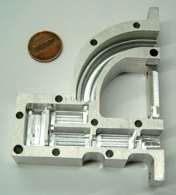
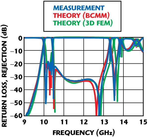
The advantage of the MM method can be demonstrated using the example of an asymmetric four-pole bandpass filter in integrated waveguide technology (see Figure 3). To achieve full convergence of the results, it is necessary to include all modes up to a cut-off frequency of 200 GHz for the application of the BCMM method. This leads to a CPU time of about three seconds per frequency. The result of this computation is shown in Figure 4. Excellent correlation to measurements is achieved.
Using a conventional frequency sweep, 400 samples are needed for reproduction of the curves, leading to a total CPU time of 20 minutes. Using the new, adaptive frequency interpolation, the same results are obtained with the computation of 30 frequencies only, leading to a reduction of a factor of 13 in CPU time.
Also included in Figure 4 are the results of the 3D FEM simulation of the filter carried out by the new integrated 3D FEM simulation feature. Although a similar reduction can be achieved in the number of frequency samples, in this case the CPU time for a single frequency is approximately 22 seconds, although the match of the results is not as good as obtained with the BCMM method due to a small frequency shift and distortion in return loss.
For this computation the same breakdown of the structure into single elements has been used as with the BCMM method, and each element has been analyzed separately using the 3D FEM method, which involved about 125,000 unknowns in total. This scenario is comparable to the case when a circuit is analyzed with the μWave Wizard, but no parts of the circuit are suitable for the MM method. Even so, these CPU time ratio results are better than can be achieved when the 3D FEM calculation is being executed in one single step for the entire structure as occurs in conventional 3D EM simulators.
Conclusion
The new μWave Wizard version 6.5 delivers good performance and accuracy to the engineers designing passive microwave and RF circuits. It achieves this goal through the combination of fast EM solvers based on the mode matching method in combination with fast adaptive frequency interpolation. Furthermore, Mician offers support and software updates that incorporate new features and design elements.
Additional information can be obtained via e-mail at sales@mician.com.
Mician GmbH,
Bremen, Germany,
+49 (421) 168 993 51, www.mician.com.
RS No. 303