
Mobile communications devices are becoming smaller in order to afford efficient mobility. Antennas, which are used to transmit and receive signals, are also increasingly required to become smaller and lightweight, while maintaining high gain characteristics. Generally, small antennas are electrically and physically undersized. A number of design methods can be used to fabricate such antennas.
A method that is widely used at present to miniaturize geometrical structures and increase radiation uses a parasitic element.

The quality factor of small-sized antennas increases due to the proximity of a grounding surface and the high electric current density, reducing the bandwidth.
Meanwhile, an increase in the electric current density causes the impedance to rise, increasing Joule losses, and thereby decreasing the antenna’s gain.1 Existing dual monopole antennas generate a mutual inductance, typical of a radiator with a monopole structure.
This has a negative influence on the radiation efficiency of the antenna, as it increases the reactance.
Therefore, in this study, both ends of the monopole structure are folded in order to reduce the impedance value.

This is accomplished by generating a capacitance from coupling between radiators, which results in a sufficient increase of antenna efficiency as well as operating bandwidth.
A planar printed structure in the form of a microstrip antenna is also employed. This structure yields cost benefits, as it is capable of being mass-produced.
The antenna also offers a wide range of application owing to its light weight, compact design and printed circuit board manufacturing technique.2–4
An operating frequency bandwidth of 2.07 GHz (1.98 to 4.05 GHz) with a VSWR less than 2 was obtained. Consequently, the wideband dual monopole antenna can be used for WLL (wireless local loop), WLAN (wireless local area network), 2.4 to 2.48 GHz, satellite DMB (satellite digital mobile broadcasting) 2.63 to 2.655 GHz and ISM (industry science medical).

Antenna Design
Figure 1 shows the geometry of the modified folded dual monopole antennas proposed in this article; h is the height of the dielectric substrate and t is the conductor thickness. The proposed antenna characteristics were analyzed with L1, L2, G1, G2 and HG as variables. A 0.8 mm thick FR-4 substrate with a dielectric constant of 4.6 was used for the proposed antenna design.
The antenna has a dual monopole structure with a 50 Ω coplanar waveguide feed. The relative dielectric constant used for microstrip antennas is usually in the range of 2.2 to 12.
Because the microwave circuits connected to the antenna require high dielectric constants and thin circuit boards, there are mutually exclusive requirements between good antenna performance and circuit design with a small structure.
In the case of a small antenna, the impedance bandwidth is particularly narrow due to the high impedance.
To allow for wideband characteristics, both ends of the dual monopole are folded, as shown in the figure. This, in turn, leads to the generation of coupling on the radiator, dispersing the current density and reducing the impedance, thereby enhancing the antenna’s overall performance.
Characteristics of the Folded Monopole Structure
When the ends of a dual monopole are folded, the capacitance between the radiators increases, which enhances the gain and impedance bandwidth of the antenna.
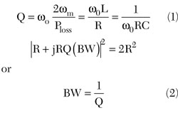
A comparison of the characteristics of the proposed antenna with those of a conventional antenna, in terms of reflection coefficients and radiation patterns, shows that the proposed antenna increases the operating impedance bandwidth by more than a factor of two. Generally, as dictated by the relationship between the Q value and bandwidth as given by Equation 1, when the ends of a radiator are folded the total inductance is reduced due to the mutual inductance, while the capacitance is increased due to coupling. The bandwidth (BW) increase can thus be identified through changes in L and C.
In addition, with the folded radiator, the size of the antenna can be reduced.
Fabrication and Measurement
The proposed folded dual monopole structure was analyzed by varying the value of each parameter. Figure 2 shows the simulated reflection coefficient as a function of G2 with G1 and HG fixed at 1.5 and 2 mm, respectively, while G2 varies from 0.5 to 2.5 mm.

The best resonance characteristics were achieved when G2 was equal to 1.5 mm. While there was no significant change in bandwidth due to the changes of these values, the reflection coefficient did change. First, for G2 = 0.5 mm, the resonance characteristics were unfavorable, but they improved steadily as the value of G2 increased, showing the best resonance characteristics at 1.5 mm.
They then started to deteriorate when the value exceeded the 1.5 mm level.
Figure 3 shows the reflection coefficient when the G3 value was changed from 2 to 12 mm. Here, the values of G1 and G2 are fixed at 1.5 and 2 mm, respectively.
As shown, when the value of G3 increased, the resonance band moved toward a higher frequency.
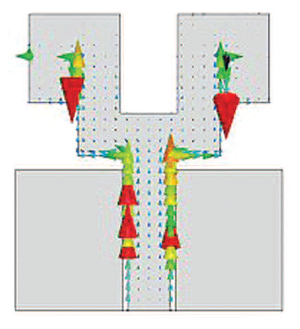
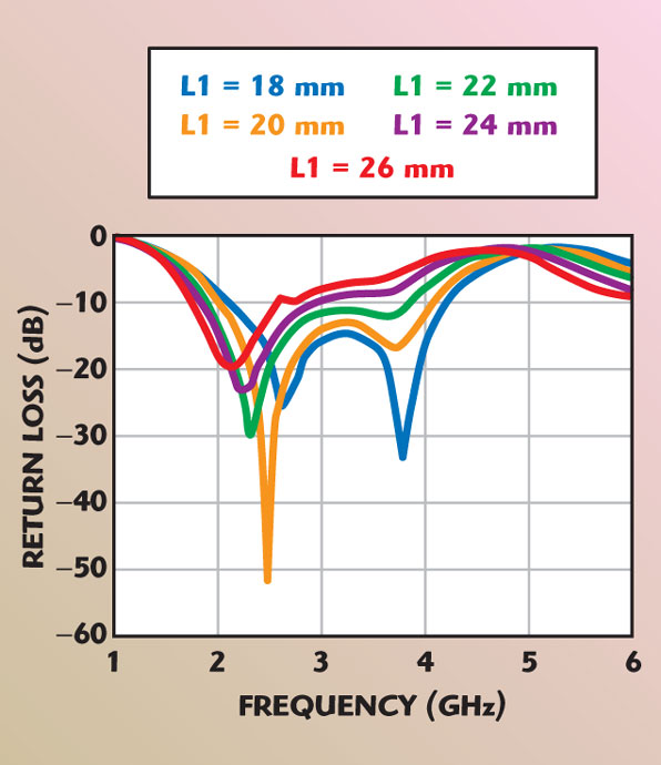
Figure 4 shows the reflection coefficient when the value of L1 was increased by increments of 2 mm from 18 to 26 mm.
When the value of L1 was 18 mm, a satisfactory dual resonance characteristic was obtained, whereas when the value was greater than 20 mm, satisfactory resonance characteristics were found only at the lower frequency band.
This is presumably because the length of L1 exhibited different characteristics at the higher and lower bands, due to different resonance conditions.
Moreover, the increase in the L1 value resulted in resonance generated among lower frequency bands as the antenna’s total length increased. Here, the G1, HG, G2 and G3 values were set at 1.5, 1.5, 2 and 2 mm, respectively.
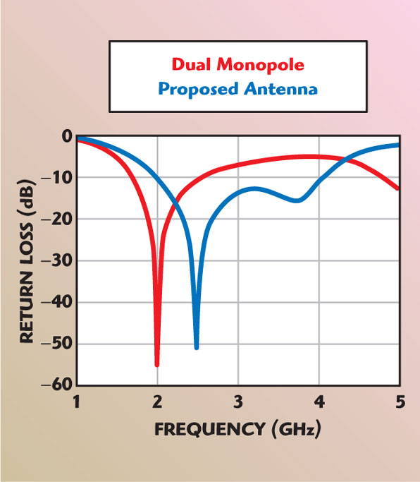
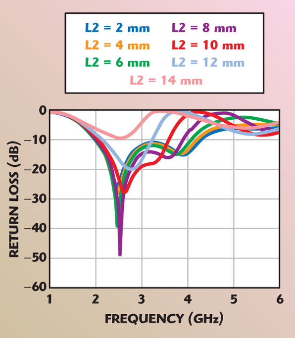
Figure 5 shows the reflection coefficient as a function of L2. When the L2 value increased, the bandwidth decreased at the higher frequency.
As was expected, this is attributable to the increasing length of the antenna. Also, with the changes in operating frequency bands, the resonance characteristics deteriorated, which can be explained by the parasite elements generated between L1 and L2.
Table 1 gives the optimum values obtained from the simulations.
Figure 6 shows the current distribution within the proposed folded dual monopole antennas. As shown, the current density caused by coupling becomes particularly strong where the monopole is folded.
Figure 7 compares the reflection coefficient between a conventional structure and the proposed structure. As shown by the equation,

regarding frequency and reactance in a resonant circuit, a reduction of the inductance value increases the resonance frequency.
As a result, while the conventional structure showed an impedance bandwidth of 600 MHz (1.8 to 2.4 GHz), the proposed structure resulted in a 2.04 GHz bandwidth (1.98 to 4.05 GHz).
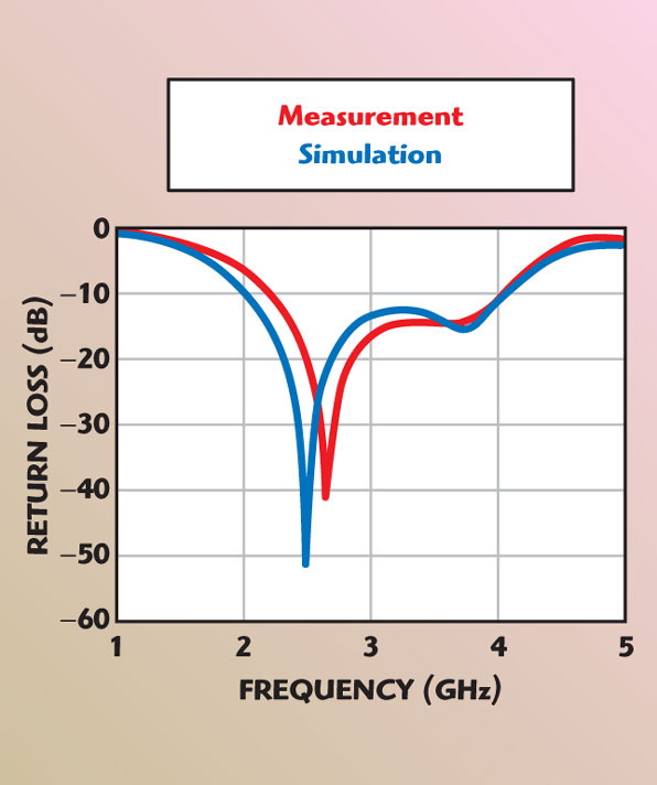
Figure 8 compares the measured and simulated reflection coefficients of the proposed antenna. While the two sets of values are in close proximity, there are slight discrepancies.
These are attributed to errors during the fabrication process in the laboratory. The antenna should have been constructed such that there is no difference in the phases between the two waveguides.
Figures 9 and 10 show the measured radiation patterns at each frequency band. As indicated by the solid line of the E-plane and the dotted line of the H-plane, they show a typical omni-directional radiation pattern as well as satisfactory pattern characteristics.
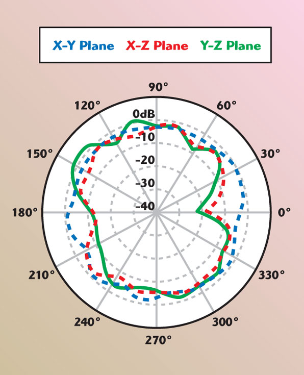
The radiation patterns were measured using Star Gate-32.
Conclusion
In this article, a folded dual monopole antenna structure for wideband antennas with a single planar structure is proposed, designed and fabricated.
The antenna fabrication, based on the proposed design, is 42 mm in length and 38 mm in width. The proposed antenna is a wideband antenna with a bandwidth of 2.09 GHz (1.98 to 4.05 GHz), which is suitable for use in ISM, WiBro and satellite DMB.
The dual folded monopole antenna is a printed type, which offers the advantages of easy manufacturing and miniaturization.
References

- W. Menzel and W. Grabherr, “A Microstrip Patch Antenna with Coplanar Feed Line,” IEEE Microwave and Guided Wave Letters, Vol. 1, No. 11, November 1991, pp. 340–342.
- R.N. Simons, Coplanar Waveguide Circuits, Components and Systems, John Wiley & Sons Inc., Somerset, NJ, 2001.
- K.D. Katsibas, C.A. Balanis and P.A. Tirkas, “Folded Loop Antenna for Mobile Communications System,” 1996 IEEE International Antenna and Propagation Symposium Digest, Vol. 34, pp. 1582–1585.
- H.M. Chen, Y.F. Lin, C.C. Kuo and K.C. Huang, “A Compact Dual-band Microstrip-fed Folded Loop Antenna,” 2001 IEEE Antennas & Propagation International Symposium Digest, Vol. 2, pp. 124–127.